| The Snowman was inspired by Tyler Gunn’s snowman I saw the prior year while driving around looking at lights with the kids one December evening. It took a few months thinking about it and the idea to use seed pixels instead of standard bullet pixels for me to conclude a snowman needed to be added to my collection of Christmas props. |
Specs:
|
 |
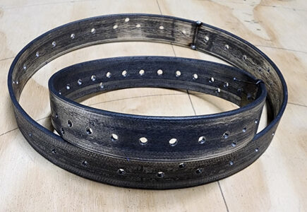 |
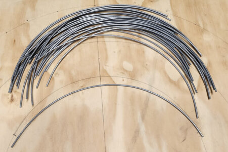
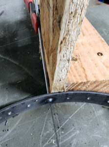
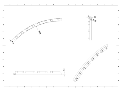
| Started each sphere by cutting to length and bending 9 ga galvanized steel wire to the required radius for the given spheres diameter. The bending is done with a small ring roller. I should note that I would have preferred to have used 7 ga wire but could not find it. | Next the top and bottom support rings for the sphere are made. This was done from 1 x 1/8 flat bar. The bar is cut to length and evenly spaced holes drilled down the center for each rib. Four additional holes are drilled to secure each quarter of the ring to a central spine. Once all the holes are drilled the bar is then rolled into a ring and the ends tack welded. The idea here is once the sphere is complete the support rings can be cut into quarters for better storage. In hind sight I would have not placed the rib holes down the center of the bar and would have instead placed them down one edge to reduce the gap between the ribs of the spheres once they are stacked. Note that the top ring is of a smaller diameter than the bottom ring to better align with of sphere above when stacked. |
 |
 |
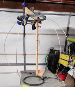
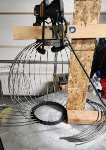
| used some scrap wood to support and align the top and bottom rings while the rib wires are being attached. | The ends of the ribs get inserted into the holes of the top and bottom rings |
 |
 |
 |
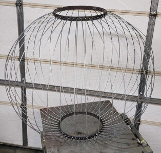 |
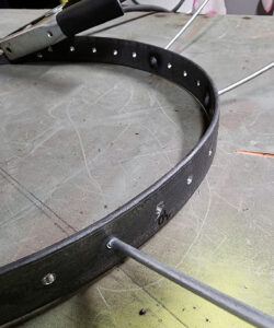
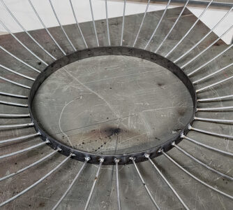
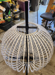
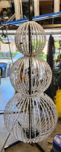
| ribs get welded to the support rings from the outside along with plug welded from the inside of the ring. | Completed sphere. The support rings get primed and painted white, while the ribs were left unpainted as they are protected from rusting by the galvanized coating of the wire. |
 |
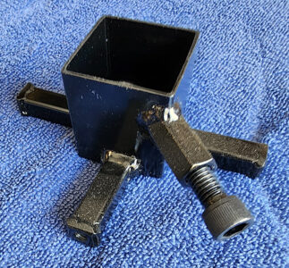 |
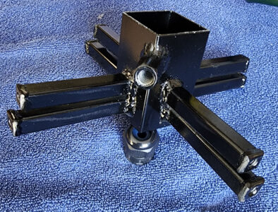
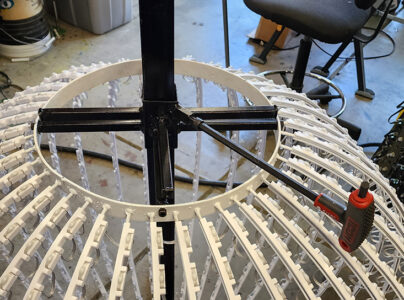
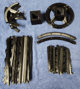
| Brackets are needed to secure the spheres to the central support column and assemble the spheres into spheres after they are cut into quarters for storage. These are made from 1 3/4 square tube so they fit over the 1 1/2 center column. The arms the sphere attach are 1/2 square tube with 1/4-20 weld nuts attached to the ends, allowing the sphere quarters to be bolted to the bracket. A coupling nut is attached to one corner to allow for a bolt to lock the bracket to the center column. | |
 |
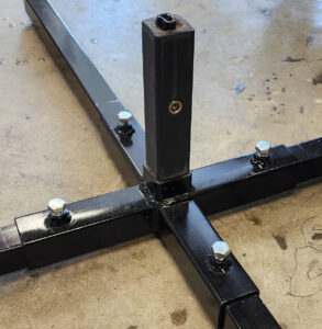 |
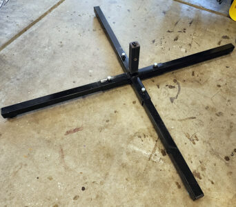
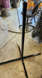
| The central yoke of the base is made from 1 3/4 square tube with a 0.95 wall thickness to allow 1 1/2 tube to nicely fit inside. However the center column is made from 0.063 wall tube for weight and i had a bunch. | For the vertical riser from the yoke, do to the thinner wall tube in the vertical column I covered the pin with medium wall heat shrink tube to work as a spacer. This need will depend on the tube sizes and wall thickness used. A side benefit is that the shrink wrap makes for a nice covering that prevents paint from getting scrapped off while sliding the vertical column on and off the yoke. |
 |
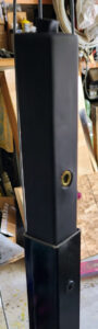 |
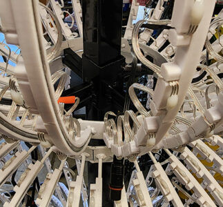
| Do to size the vertical column was split into two parts to make stacking the spheres easier. | The vertical column is joined with a pin made from 1 1/4 square tube again covered in shrink tube as a spacer. Rivet nuts are used in the pin to allow the column halves to be secured. Flat head screws are used here to keep from interfering with the sphere brackets that need to slide over the column tube. |
  |
 |
| While the metal armature was being built, the 3d printer was working overtime to print the clips that snap onto the sphere ribs and hold the seed pixels. These clips need to be adjusted for the diameter of the sphere. | |
  |
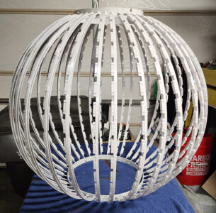 |
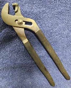
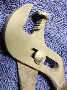
| Took some old pliers and welded a small piece of 1/8 steel to make a tool to help pressing the clips onto the wire ribs of the spheres. In hind sight channel style pliers were not the most ergonomic choice and I should have use normal pliers as the base donner. | The spheres really start looking like something once all the clips have been attached. I did find that variances in wire diameter from different lots and the bridging that happens at the top of the circular slot in the clips sometimes made the snap fit of the clips not great so I ended up putting three small drips of glue in the channels of the clips prior to snapping them onto the wire ribs of the spheres. I found this really improved the rigidity of the ribs in the end. |
| To the right are links to the clip files, though you will likely need to adjust for wire/bar size and diameter of spheres being used. Definitely do some testing before spending hundreds of hours printing clips. For example the bottom sphere is 36 inch diameter with 40 ribs and requires 240 clips. | |
 |
 |
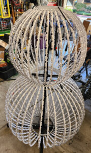
| Time to stack the spheres on the base and support column | |
 |
 |
 |
|
 |
 |
 |
|
 |
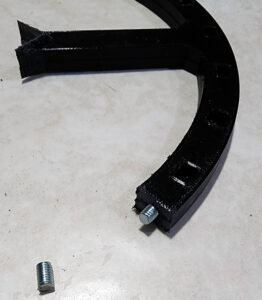 |
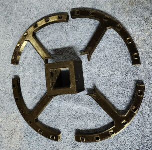
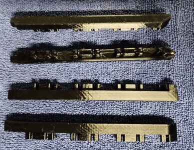
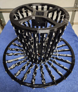
| The upper ring of the hat had to be split to fit on the build plate | Assembly of the upper ring is done with CA glue and metal pins for added joint support. For pins I used a 10-32 screw cut into about 5/8 lengths. Was just a fast way of using what I had on hand, but in hindsight the threads allow for a lot of glue surface. |
 |
 |
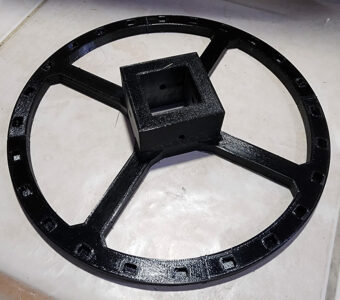
| Lower ring was made to just fit the printers build plate so it is all one piece | |
 |
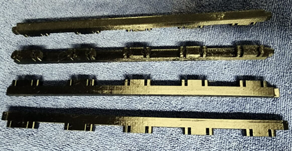 |
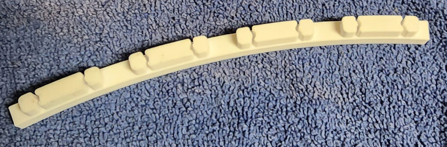
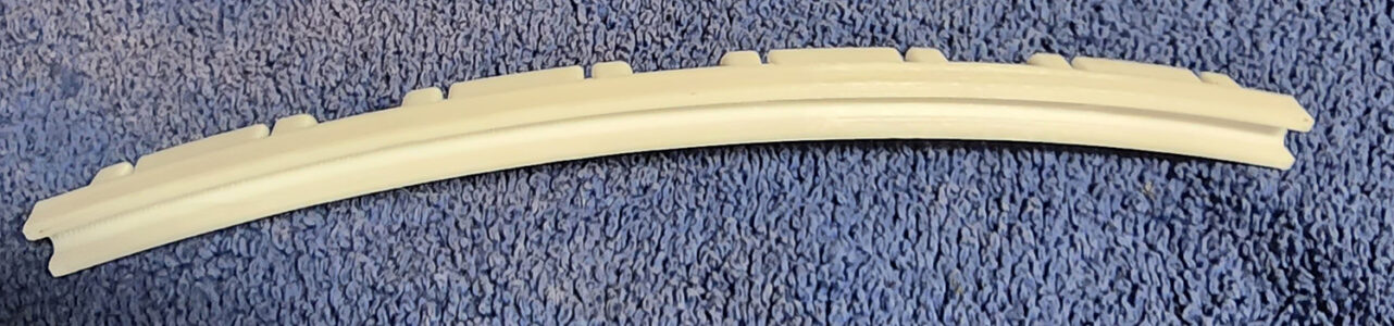
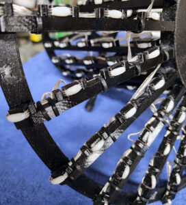
| Closeup of the ribs for the brim. The seed pixel clip portion was scaled down for these ribs and ended up holding the pixels a bit loose, so I ended up using a few cable ties to secure the pixels and hold the wire down to the ribs to keep the brim of the hat from looking like a total mess. | Close up of the ribs for the hat. Each has 5 seed pixels and tabs that slide into the upper and lower rings. |
 |
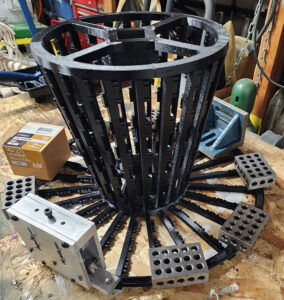 |
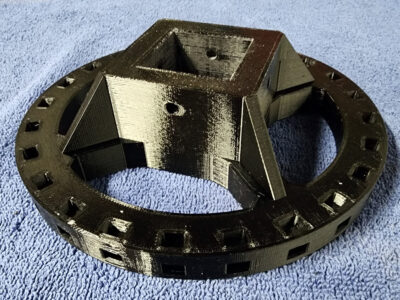
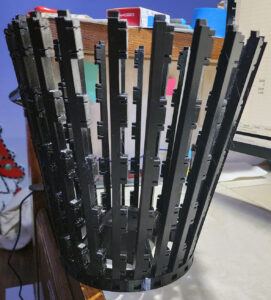
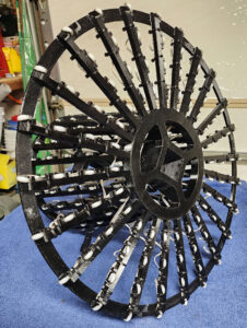
| started by inserting the vertical ribs into the lower ring with a drop of CA glue. The glue was likely overkill as the ribs are a press fit into the upper and lower rings. The upper ring gets added next with special attention to make sure the inner square holes for the center column are aligned. Following the main hat body, the 24 brim ribs were attached to the lower ring, again with a drop of CA glue. | With all the ribs attached, the brim support ring was added. A drop of glue was used for each rib to support ring intersection. I had originally planed to use small screws for this but just used glue in the end. If just using glue plan ahead (unlike me) and have some clamps or weights ready to hold the support ring and ribs together while the glue sets. |
 |
 |
 |
Pixels are done in vertical pattern around the hat body and then around the brim with a skipping pattern down and back each rib. |
| Files for printing a hat. Note the hat has 24 body and bring ribs. | |
 |
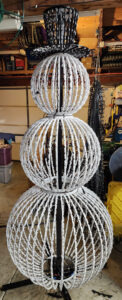 |
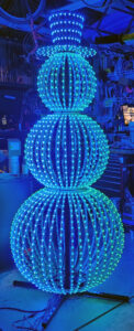
| Let’s get the Hat added to the stack-up on the central column. | Well, here it is standing a bit over 7 1/2 feet tall. |
 |
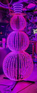 |
| Testing to make sure all the pixels are working and connections are good. Power is injected many places from a central power only line that runs up the central column. |