 |
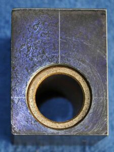 |
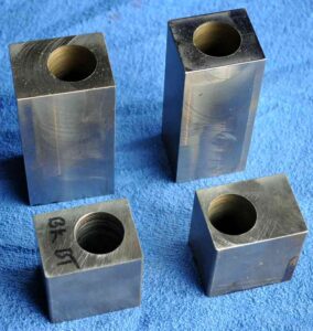
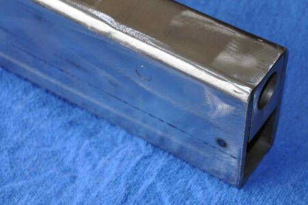
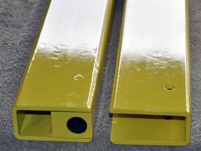
| I started with creating the bushing housings. These are sized to slip into 2 x 4 tube with a .25 wall thickness. After struggling to drill the first blocks inch diameter hole I elected to outsource the other three holes. | example of housing with bronze oil embedded bushing installed |
 |
 |
 |
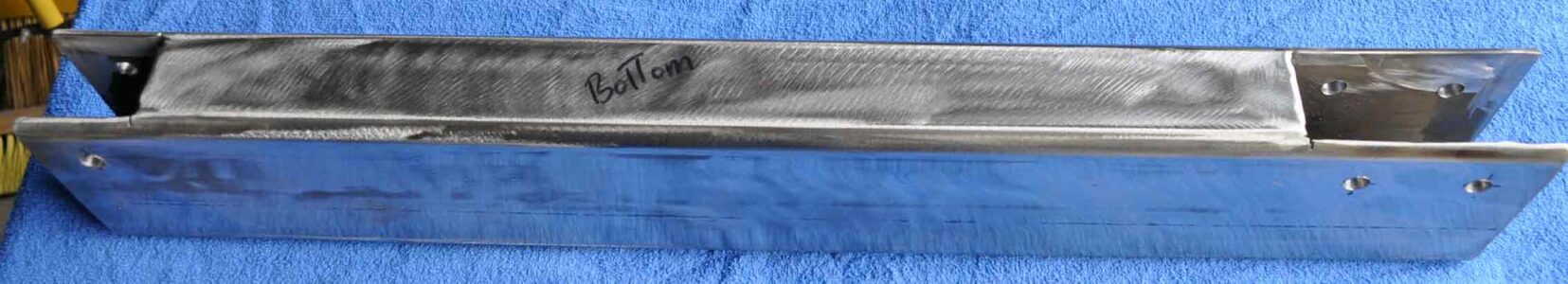
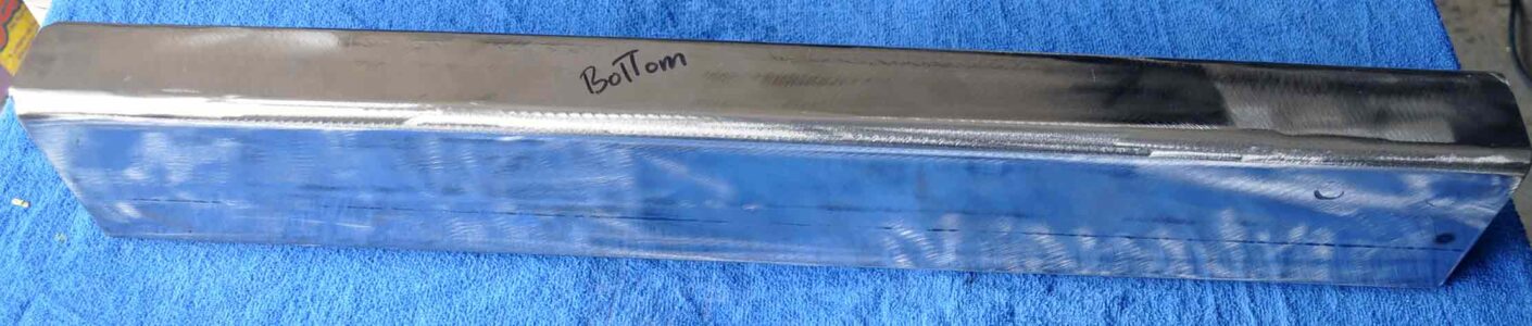
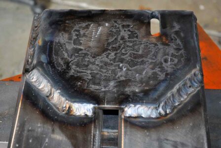
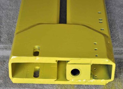
The lower support arm showing cutouts for flush mounting the bushing blocks that need to get welded in. Note that the 3/8 holes in the side of the tube are for welding the blocks to the side of the tubes as getting to the back side of the block inside the tube is a challenge. above and left are the tube post welding and grinding to smooth and round the sharp corners of the bushing blocks. |
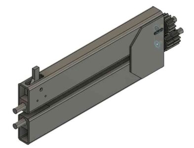
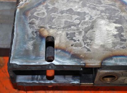
| For the upper tube the bushing blocks need to float inside the tube to allow for adjustments. Note the slot at the back to allow about an inch of in/out adjustment of the dies. At the front a 1/2 in pivot and a cutout in the top is for the bell crank and pressure adjusting knob. | 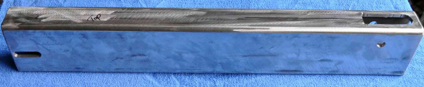 |
| Again the top tube is cut with clearance openings for the bushings to move while allowing max clearance between the upper and lower arms for work piece clearance. | 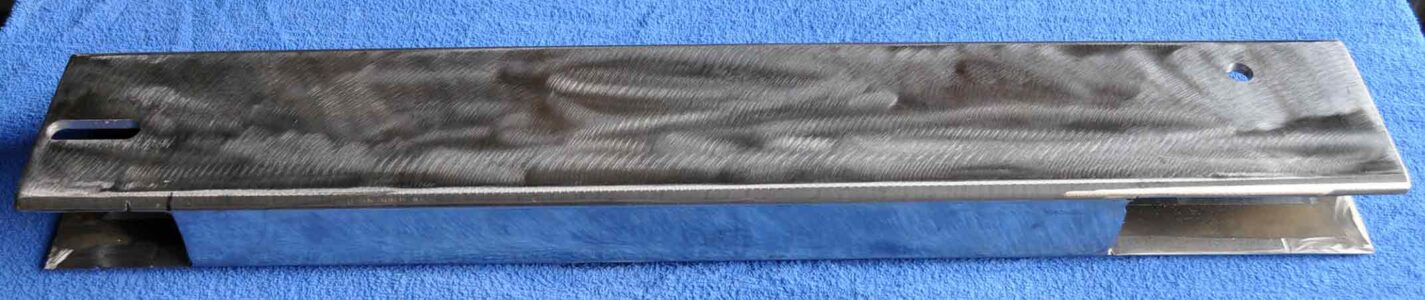 |
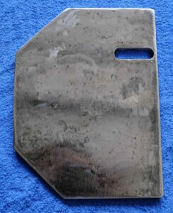 |
Next came the plates that will secure the upper and lower tubes together and hopefully prevent flexing. These are cut from 5/16 plate. The slots get aligned with the slots cut in the upper tube prior to being welded to the tubes. |
| The start of the bell crank drilled 1/2 inch and cut from 3/4 thick plate. From here the lever will have a threaded nut welded on the right bottom side. The nut provides the means for a threaded knob to apply clamping/bending pressure to the dies while quickly pivoting or releasing that pressure for repositioning the work piece. Most rollers I have seen use a fixed nut for adjustment that has to be undone and retitened to adjust the material. This mod I came across allows the pressure to be released then reapplied the exact same after repositioning the work piece. | 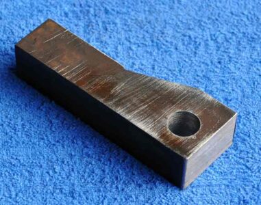 |
 |
 |
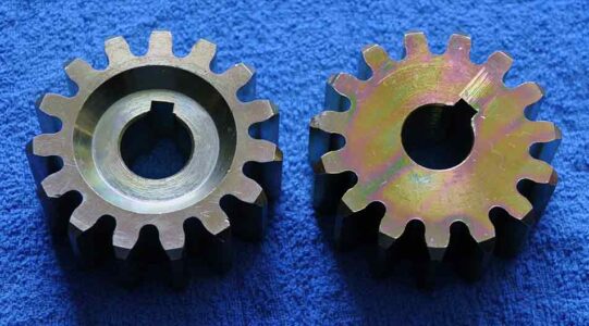
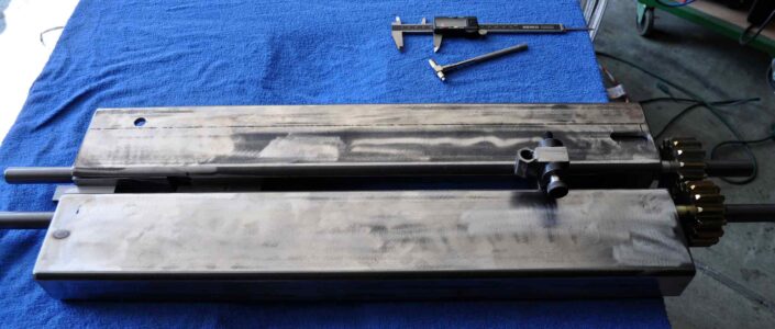
| Two of the gears for linking the upper and lower shafts. These will yield the drive shafts to be 59 mm apart when parallel. | rough lever for setting roller pressure. |
 |
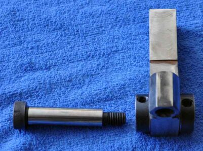 |
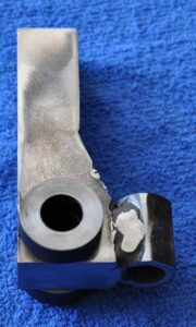
| Validating parts and spacing between upper and lower sections prior to adding the plates for joining the upper and lower bodies | cleaned up lever for setting roller pressure |
 |
 |
| plates welded locking upper and lower sections | Note that the slots have to be aligned so shaft slide will properly work |
 |
 |
| With the main body completed it became a great time to apply some paint prior to final assembly | |
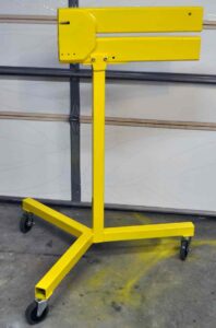 |
Roller body mounted to roller stand and ready to have the guts installed. |
 |
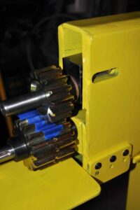 |
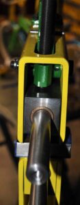
| upper drive roller installed along with green lever that applies or released pressure. With the lever locked in place pressure is increased or decreased by turning the t-screw. Pressure can be quickly released by unlocking the lever to reposition ones work piece and reapplied without counting turns of the screw. | On the other end we can see the gears mounted. Below the shafts and gears is the motor mounting plate. |
 |
|
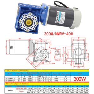
| Motor I am using to drive the bead roller | |