 |
 |
|
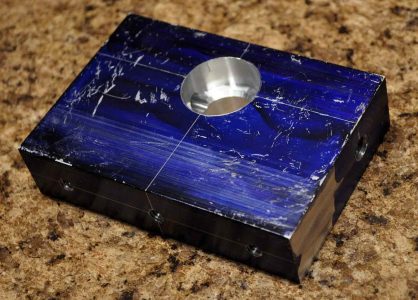
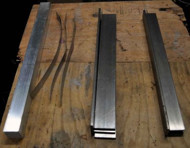
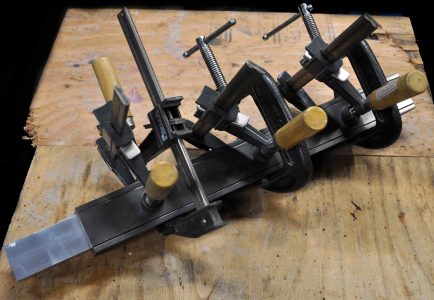
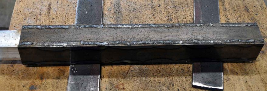
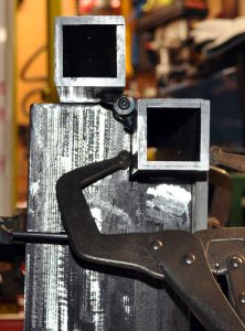
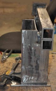
Time to get started. I am using 1/4 thick plate or bar for most elements to aid in the overall rigidity of the final tool.For the adjustable arm sockets I am electing to weld up 2 inch cold rolled bar into square tubes instead of using normal square tube because square tube has rounded corners and a internal ridge left from welding during the manufacturing process that prevents a tight fit between the receiver socket and the accessory bar. I have made up four 0.008 shims to space the flat bar away from the accessory bar during clamp-up and welding. I am expecting welding to cause a bit of shrinkage. Also I am only welding 1 inch lengths and jumping around to different places to help keep building up a lot of heat and warping the finished tube |
 |
 |
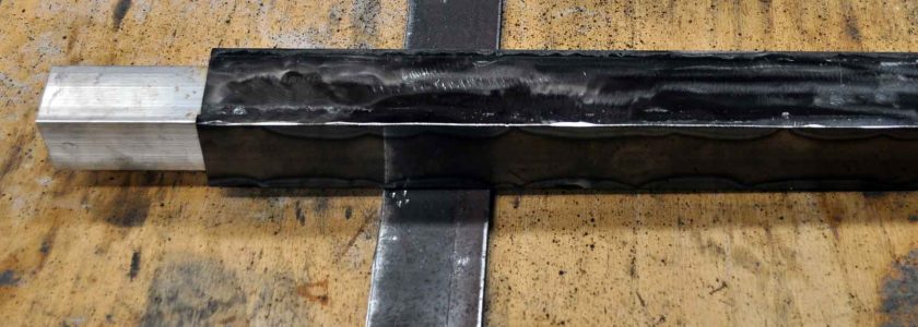 |
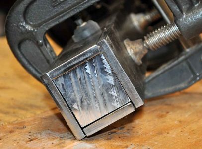
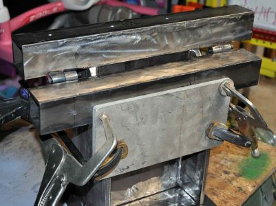
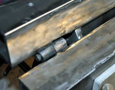
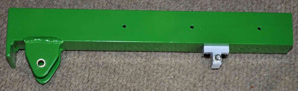
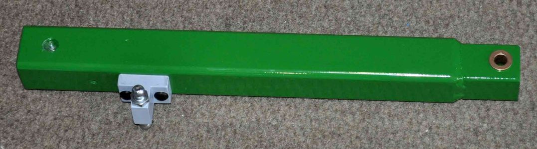
| Bars fully welded into a tube with all the clamps removed. i realized i should have looked into getting bar that was a little wider as 2 inch wide bar that is 1/4 thick does not leave any room for a 1-1/2 square bar to slide inside, so the edges of two sides of the tube are lower then the center plate. | After grinding the edges are not that pretty because they are lower than the center plate. The next fun part is removing the inner bar as welding has left the new tube tightly squeezing the the inner bar. A shop press would help here but I do not have one so i ended up using some scrap round bar and a small sledge hammer to knock the two pieces apart, and yes this took a lot of time and mushroomed the end of the scrap bar. But with the shims removed the accessory bar is a great fit in the tube. |
 |
 |
|
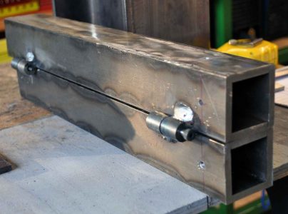
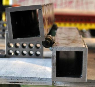
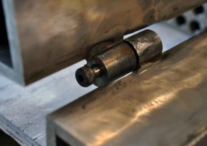
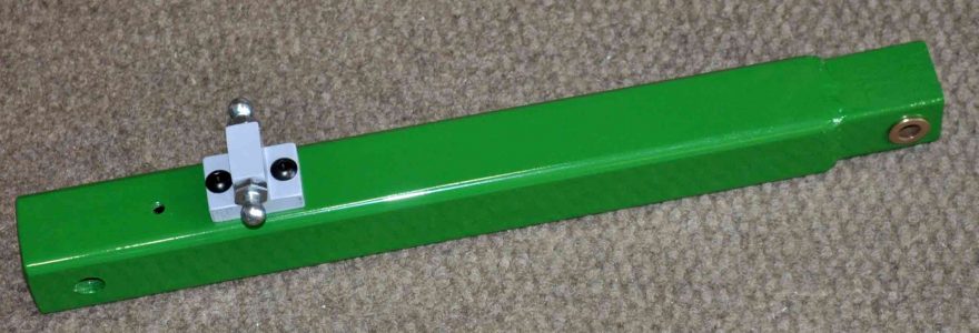
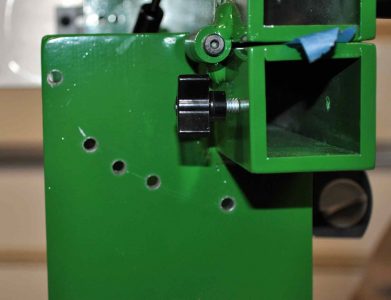
After getting the cores removed, i added some hinges. The hinges are made from some 3/4 inch round bar with a 1/4 inch hole bored down the center. Each section is about an inch long. Post welding the corner of the square tube was ground off a bit to add clearance mostly for paint. This is also a great time to start drilling holes for accessory bar clamping knobs. Always nice when parts fit in the drill press. |
 |
 |
 |
|
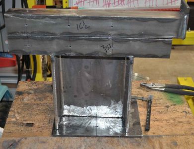
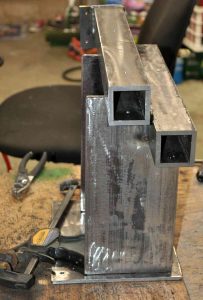
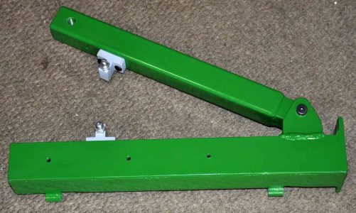
For the base I used some 8 inch I-Beam that was scrap. In hindsight I would have cut a large U shape out the the web of the I-beam to reduce weight. The rectangular cutouts for the lower tube allow the upper tube to tip 90 degrees and then be supported by the top of the beam. To ensure the lower tube was square to the I-Beam i used a piece of aluminum plate that was handy to help clamp everything into position for welding. The lower tube is welded to the I-Beam |
 |
 |
 |
 |
 |
|
Somewhere along the way I up a 3 inch square with holes taped for 1/4-20 bolts to be welded onto the the back end of the top tube for the motor assembly to later attach Eventually the 1/4 inch plate sitting under the I-Beam gets welded to the beam to make mounting the entire tool to a bench vastly easier. |
 |
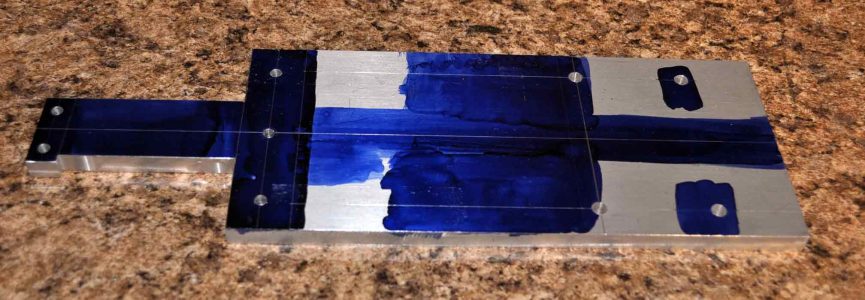 |
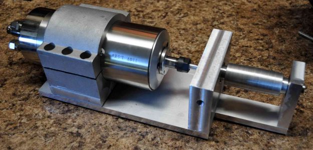
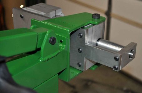
With the base welded up, it is time to focus on the motor assembly. Well really I made the tubes and then the motor assembly with the base happening a little here and there. The main part of the motor assembly is 3/8 thick aluminum plate. One end has been cut down to 1 inch wide where the drive roller sits. This section needs to be about the same width as the drive roller diameter so the sanding belt will not rub. |
|
|
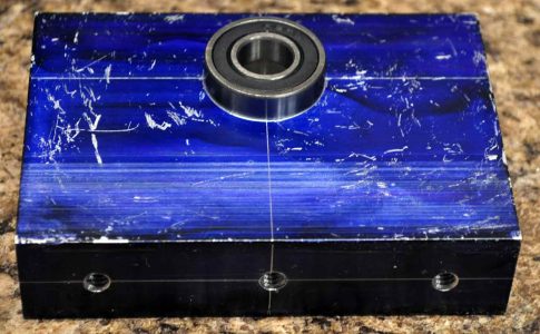 |
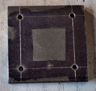
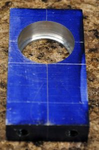
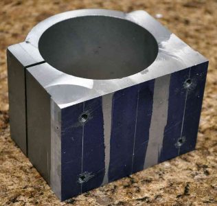
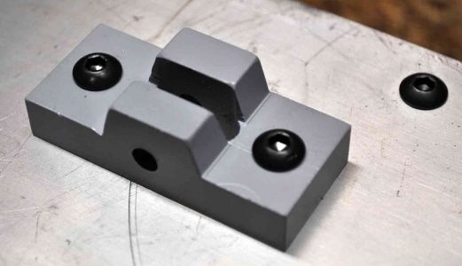
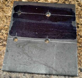
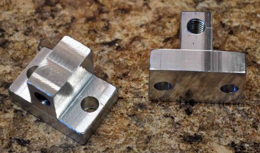
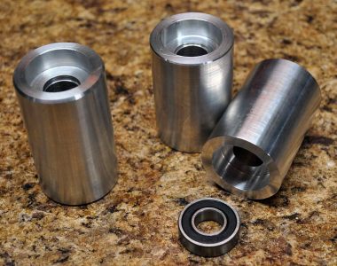
| While this bearing block does not need to be this big to support the bearing and drive roller, it was made the same width as the base plate so later the motor assembly could pivot from this point to adjust belt tracking. The three bottom hols are threaded for a 1/4-20 bolt and the sides for 3/8-16 | The bearings are a slight press fit into the blocks. The height of the bearings is a function of the size of the motor and mount being used. |
 |
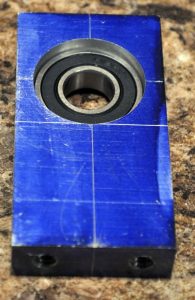 |
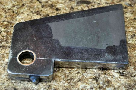
| The bearing block for the end with 1/4-20 holes in the bottom | Bearing pressed into the outer block. |
 |
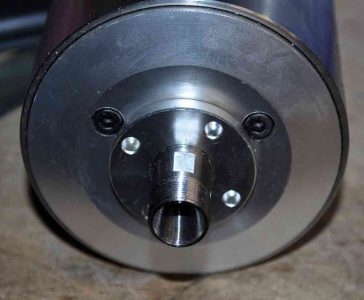 |
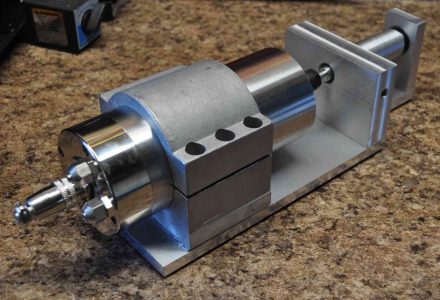
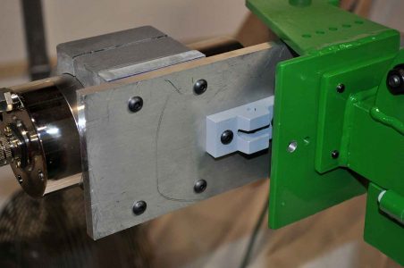
| While the motor came with a mount block, no hole were available. I suspect one would either drill holes in the flanges or clamp the flanges but to get the width down i cut off the flanges and made 1/4-20 holes in the bottom. These three parts need to be very accurately laid out on the base plate to make sure the drive roller and motor shaft are aligned | view of the motor end and spindle where the the drive roller will need to mount. |
 |
 |
|
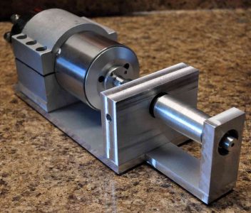
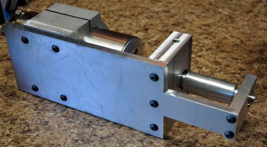
The motor assembly put together and all the layout fluid cleaned off. Depending on how good the measurements are for your motor mount you may or may-not need to shim the motor to align the height to the bearings. I had to add 0.074 in the end, guess i could have shaved the bearing mounts. The below pivot mount was later added to the bottom of the motor assembly base plate to attach a threaded rod end for belt tracking. |
 |
 |
 |
 |
 |
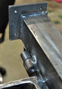
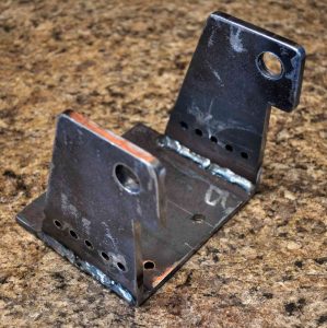
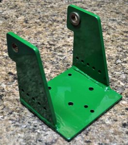
| Next up was the pivot bracket for the motor assembly. Again this is all 1/4 plate. The back piece was drilled with 1/4 inch holes that align to the mounting plate of the upper tube. The sides are where made tall enough to allow about an inch clearance between the motor plate and the bottom of the pivot bracket. For the sides I tacked two pieces of plate together and did all the cutting and drilling together so I would end up with matched sites. Large holes were 1/2 inch to accommodate the bushings. The line of 1/4 holes were originally made to provide future mounts for cable routing but proved helpful for jigging. To get the right spacing and make sure the sides are parallel I cut a aluminum block to act as a spacer during welding. | 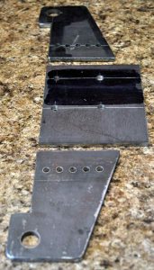 |
 |
 |
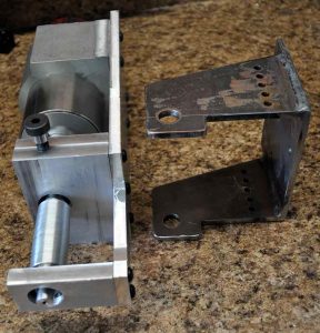 |
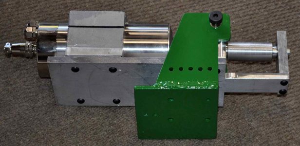
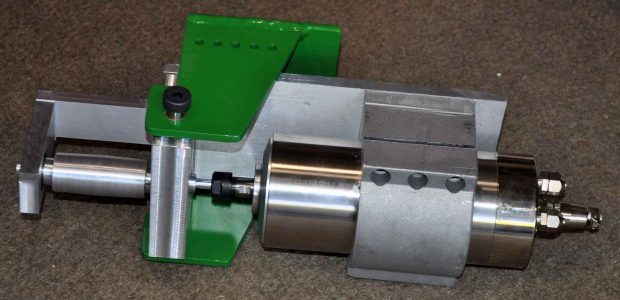
Bracket looks so nice and clean with fresh green paint Motor assembly attached to pivot bracket and ready to be bolted to the mounting plate of the upper tube.
|
 |
 |
 |
 |
 |
 |
 |
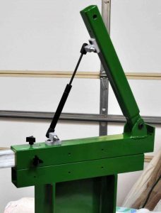
On to the belt tension arm. The above brackets attached the ball screws to the arms so that the gas springs can pivot and exert force on the belt. I am assuming I will be using two springs to help prevent any twisting of the tension arm. To the upper left are the upper tube with gas spring blocks and tabs with bushings for the tension are to attach. Just to the left is the tension arm. This is made from normal 1-1/2 steel tube with a 0.120 wall. At both ends is a piece of 1-1/4 square bar to mount the tension roller or hold bushings to pivot the arm. At the pivot end the 1-1/4 bar extends out of the square tube fit between the tabs of the upper tube that has an outer dimension of 2 inches. The mounting hole for the roller is tapped for a 1/2-13 bolt |
 |
|
 |
|
|
Here to the right is the assembled tension arm and upper tube.
Below is the tension arm assembled with one gas spring including the upper tube mounted on the lower tube. |
 |
 |
 |
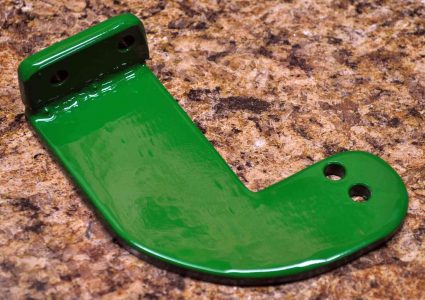 |
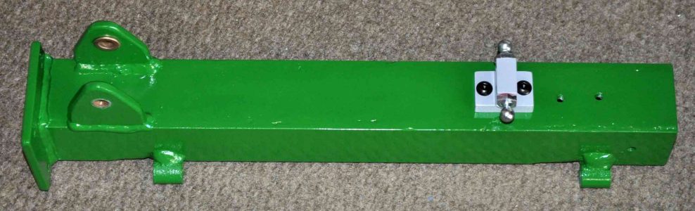
Got excited and painted the upper tube too soon. Forget to add a piece for locking the upper tube that can pivot the belt grinder from a vertical to a horizontal position. would have been so much easier to just weld the bracket to the upper tube. But as everything has paint now I have made this little bracket to the left that bolts onto the upper tub and hangs just in front of the I-Beam. The I-Beam also gets a set of 1/4 inch holes drilled to allow a pin be inserted between the I-beam and this bracket to lock the grinder in position. While i was drilling holes i also added some for 30,45, and 60 degrees just in case some day I want to have off angle grinding lines in a work piece. |
 |
|
|
Finally got around to machining the rollers for both the tension arm and platen. The tension arm roller is 2.7 inches wide and 1.6 inches in diameter. While the platen rollers are 2.3 inches wide and 1.6 inches in diameter. The diameter could be different but I got a deal on some 1-3/4 inch round bar. The bearing holes are sized for a slight press fit and are 0.400 of an inch deep leaving the bearings 0.100 recessed. The center hole is 5/8 to allow a 1/2 shaft to clear, but i am thinking i should size this up to 3/4 of an inch for better clearance of the inner bearing race and a spacer to keep the bearings from getting squeezed. |
 |
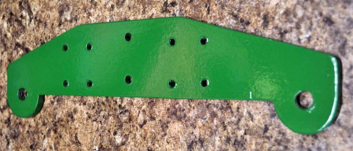 |
Frame for the platen assembly, again made from 1/4 plate. The center set of holes are 1/4 for bolting to the accuracy arm. The two sets of four holes are taped for 1/4-20 bolts to attached a piece of angle iron that will be the actual platen. The end holes taped 1/2-13 and radiused for the rollers |
 |
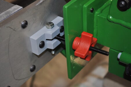 |
| Belt Tracking | |
 |
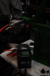 |
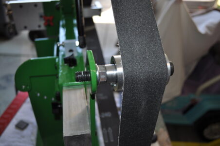
| wheels and belt ready for testing and vfd setup | VFD setup and testing |
| While the belt grinder could use some guards, I have completed the build | In using the belt grinder I find I keep breaking driver shafts where the motor collet grabs the drive shaft. I have used upgraded the aluminum shaft to a high strength steel and it continues to snap after a an hour or two of use. At this point motor shaft and driver shaft are withing 3 thou. But the metal is fatiguing and snapping, so I have to retire this design. If i build another one think I will use a large central plate with also mounts the motor and just add the drive wheel directly the motor shaft to eliminate any misalignment problems. |