| As I start making some new stuff I have found a need for having the ability to cast hollow items that seems best done using the roto-cast process. So I started looking arount for a machine to purchase or plans that I could use to build a machine, besides building the machine I find fun. However, I have only been finding youtube videos mosting showing smaller machines made from wood with a few metal ones, but with one common problem none of them detail the measurements or size of material being used. Of the videos and images I have looked over the past week most use a simulare design and the units that stand out are one build by Volin Props and another by Stelter Creative. The Stelter Creative video notes that they sell them at steltercreative.com but the web site seems to be gone, so the buy option looks to be off the table. So loosly based off some web images and videos here is my version of a roto-cast machine including the measurements and parts I am using. As always this information is for the exchange of ideas and any usage of this information is strictly at your own risk. |
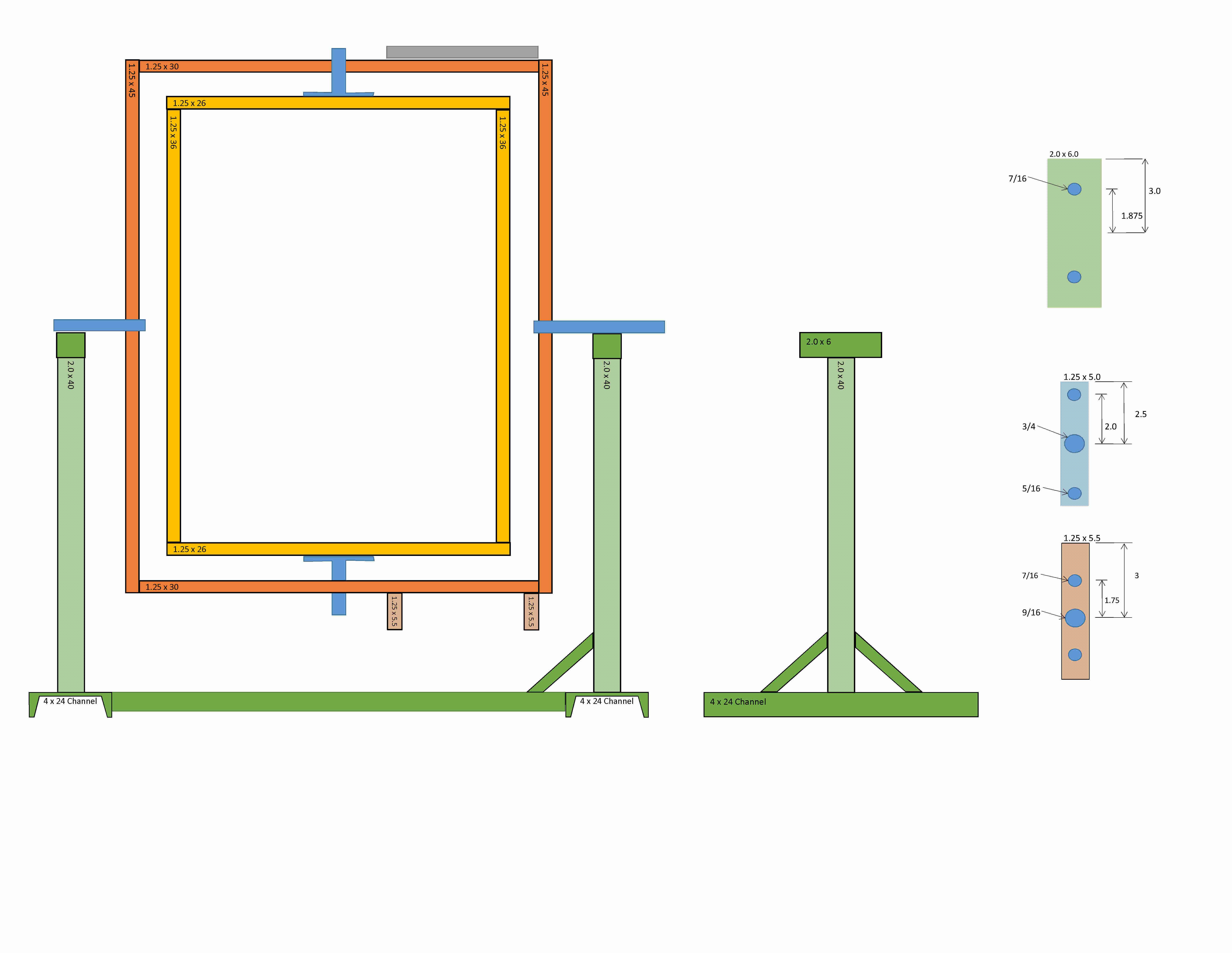 |
|
| |
|
 |
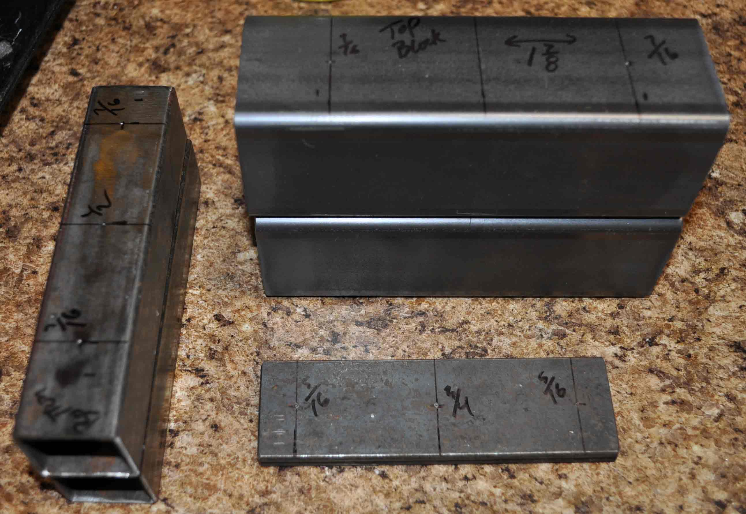 |
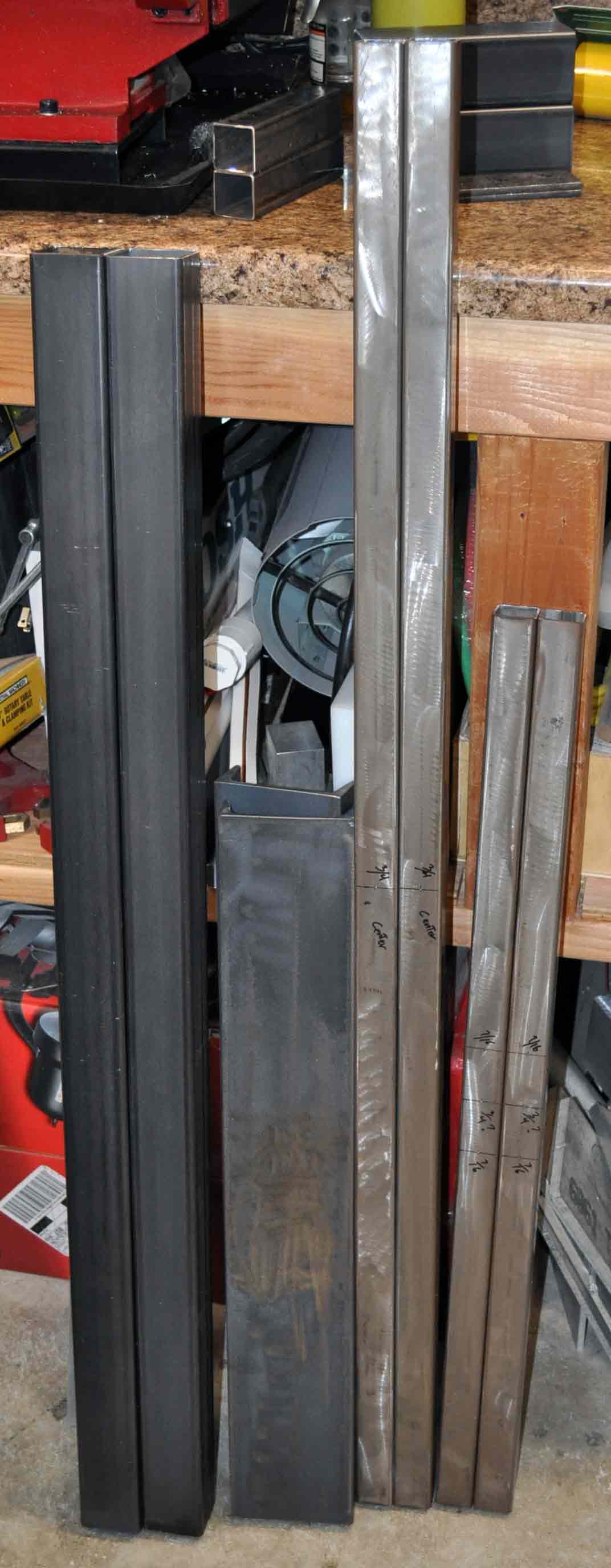
| Cut Steel – Long pieces |
Cut Steel – Short pieces |
 |
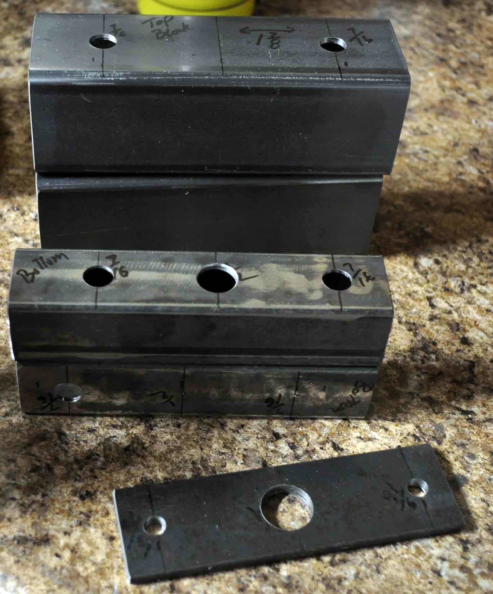 |
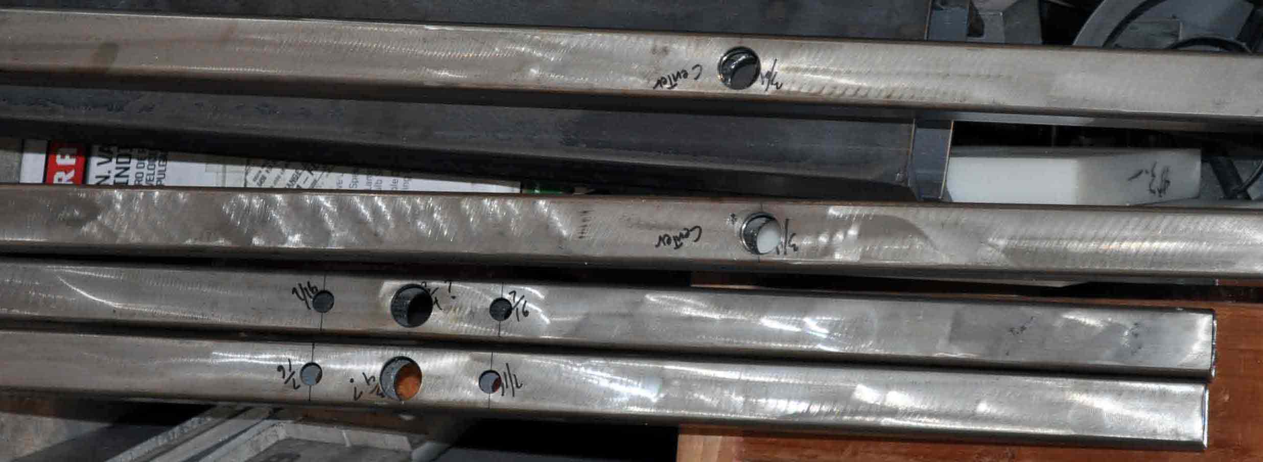
| Long peices drilled |
Short peices drilled |
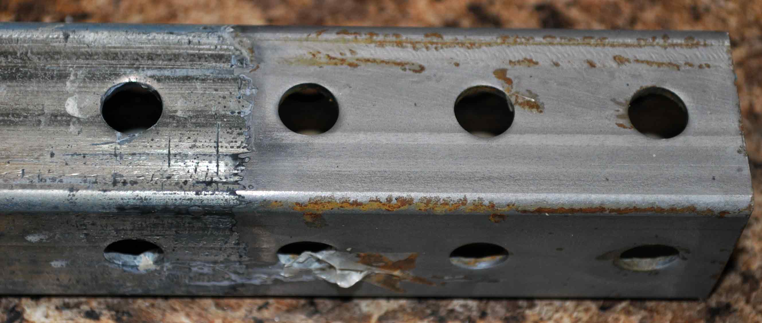 |
So I would not have to drill over 150 holes in the inner ring I have elected to use perforated square tube. The only problem is that the tube is galvanized, which generates some problems when it comes to welding. However this time I am trying a new process (for me) where the tube is soaked in muratic acid, which eats the zinc coating off the steel. As you can see in the picture to the left the shinny part on the left is still coated and the right part is a dull gray. This dull gray is the base steel with the coating removed, the acid worked but it is a bit slow but way better then trying to remove the coating with the grinder. I have only removed about 3.5 inches of each end of the tube where I will be welding pieces together. This should allow about 2 inches for the metal to cool so the zinc does not produce toxic smoke from the high heat of mig welding. |
| Perforated steel tube ready to be welded |
|
 |
 |
| The three types and sizes of mounted bearings I will be using |
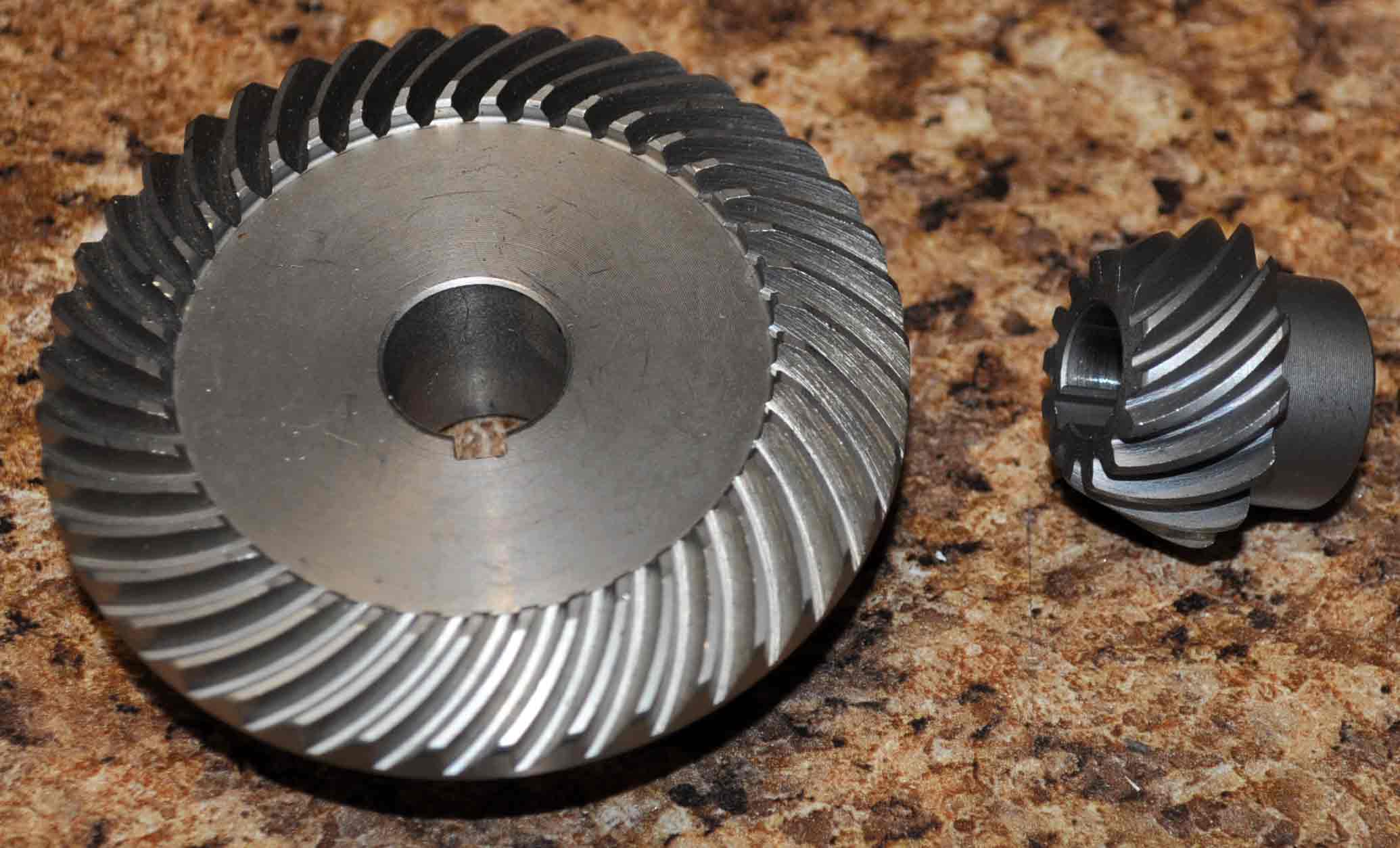
To shift rotation 90 degrees for the inner ring I am using this gear set. Originally a replacment for a small angle grinder. Just cound not beat the price |
 |
 |
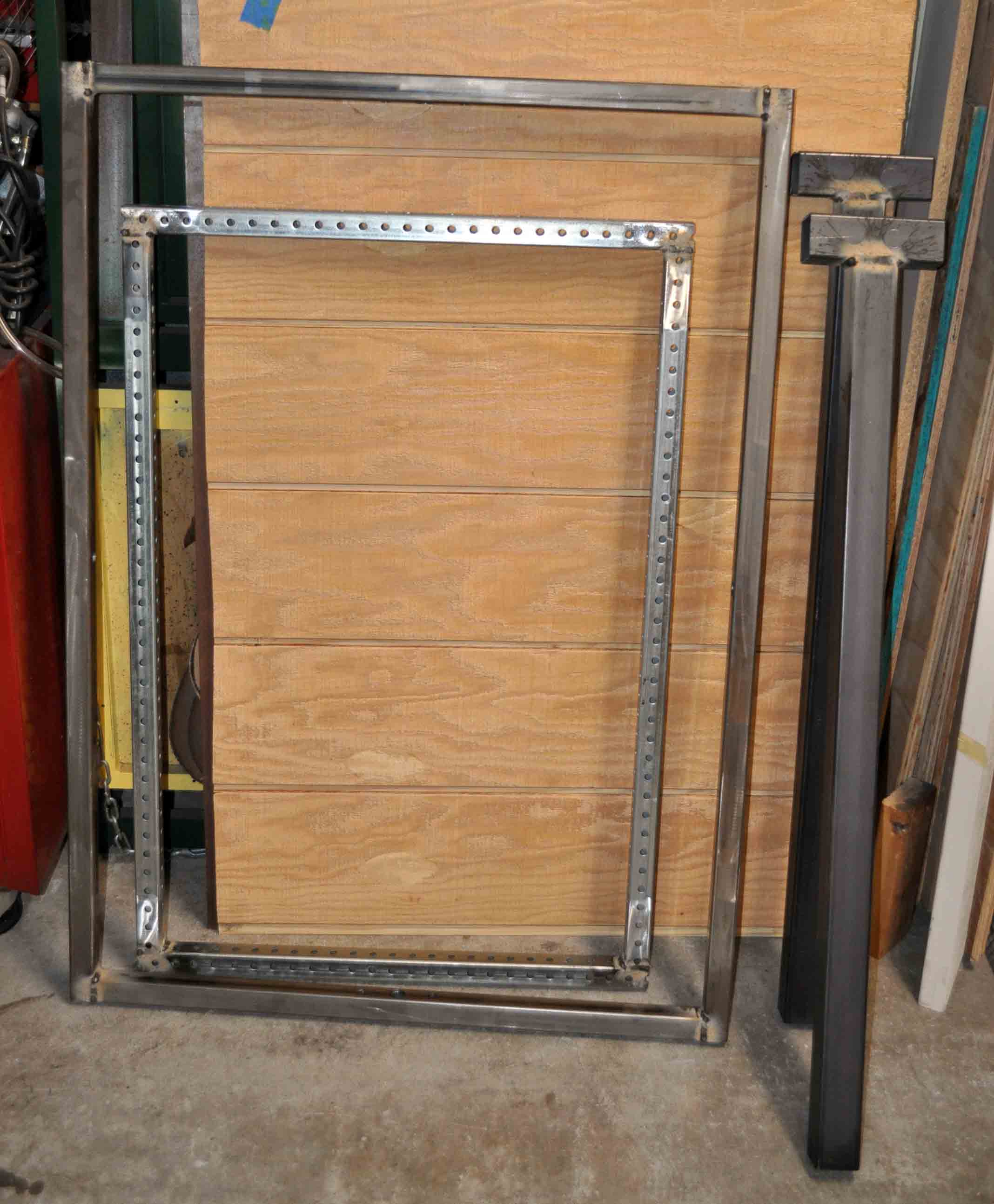
| Inner and Outer ring welded up |
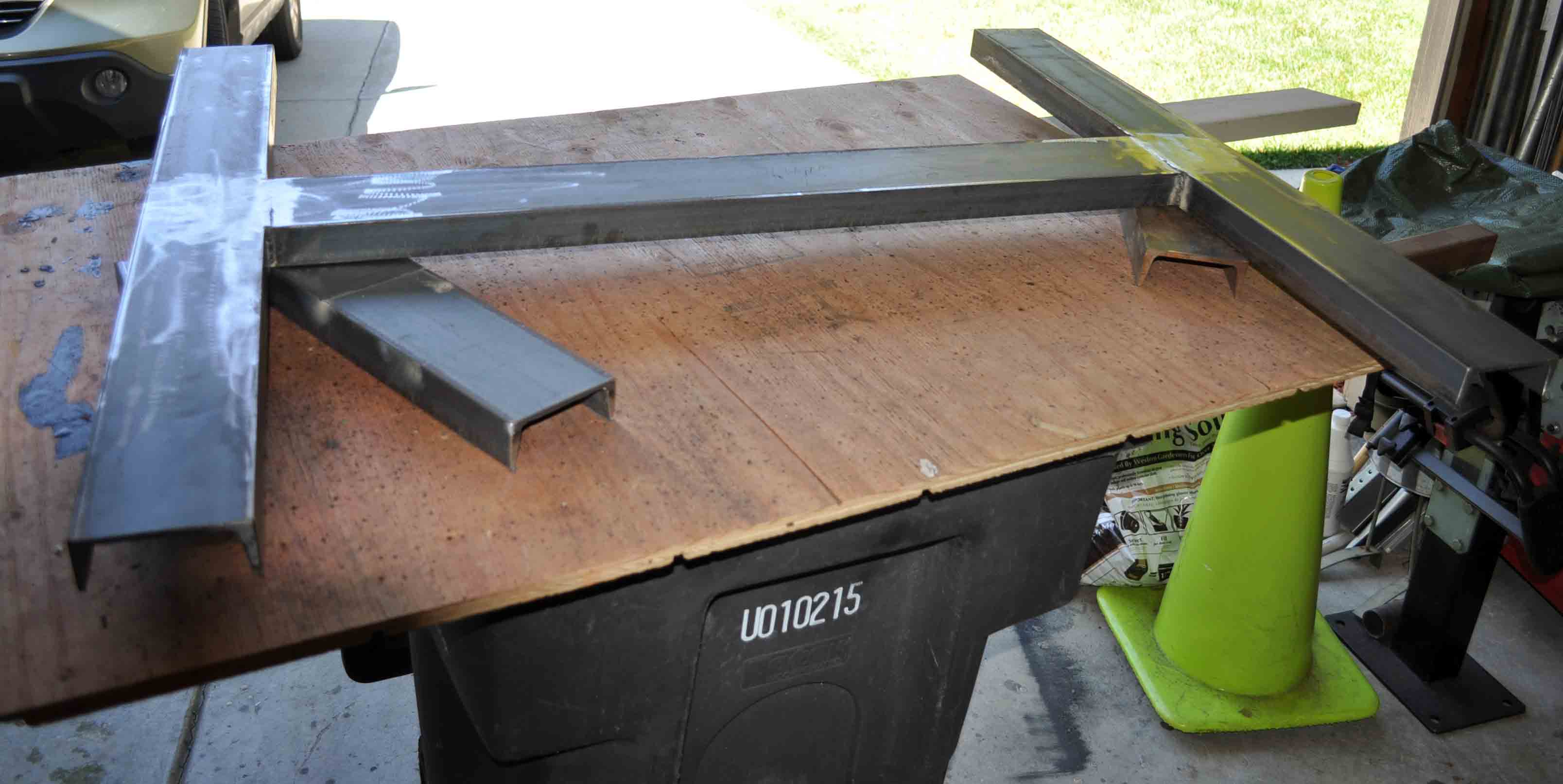
Mounting brackets for inner ring. I am doing is as I did not want to degrade the 1.25 inch perforated tube by drilling a 0.75 inch hole for the pivot bar. |
 |
 |
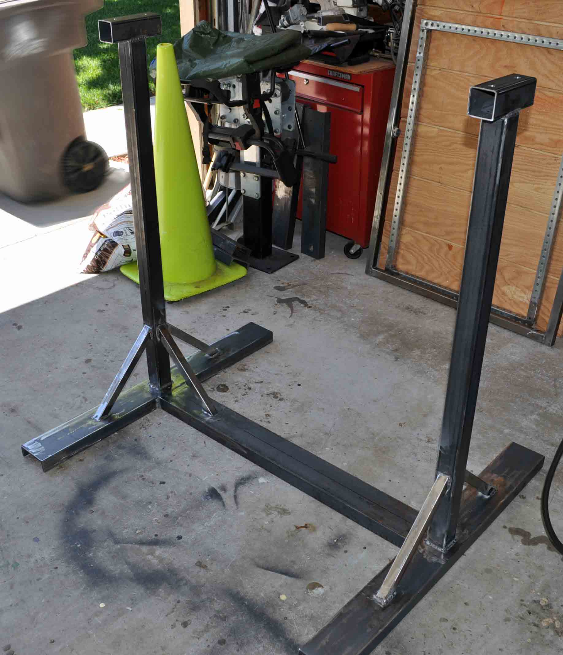
| Foot for base |
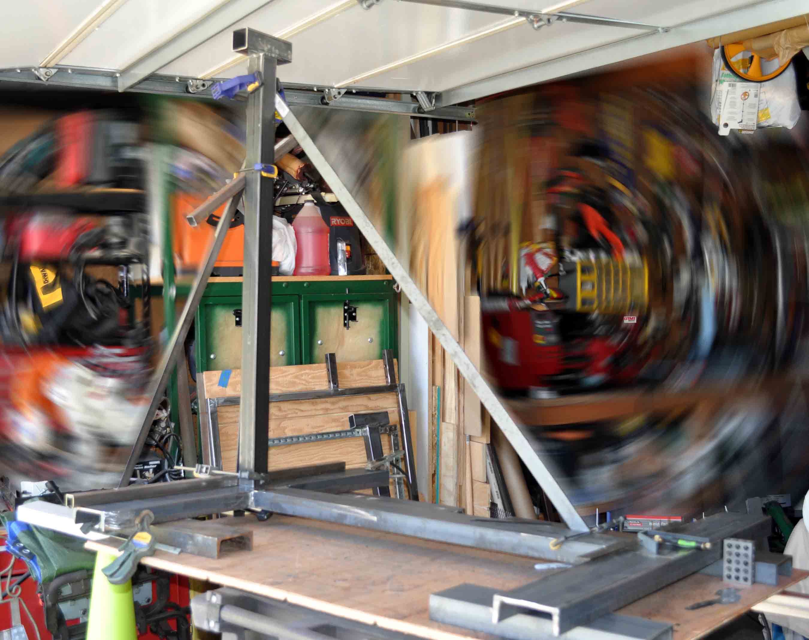
seetting up to weld the risers to the feet. Here I am positioning the riser and holding it in place with clamps and some scrap steel that was handy. It is important to get these uprights square and even to eachother. |
 |
 |
| base welded up and ready for paint |
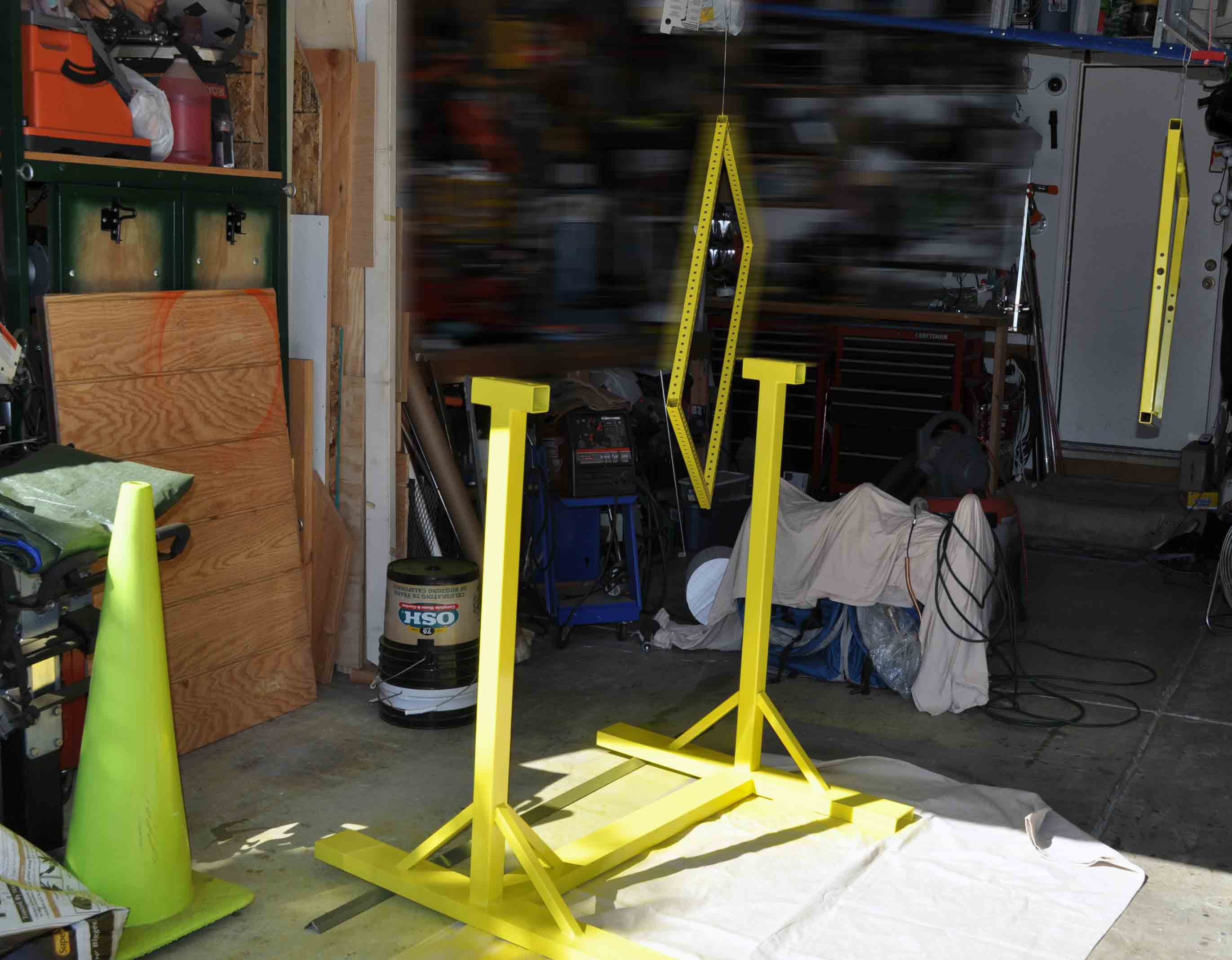
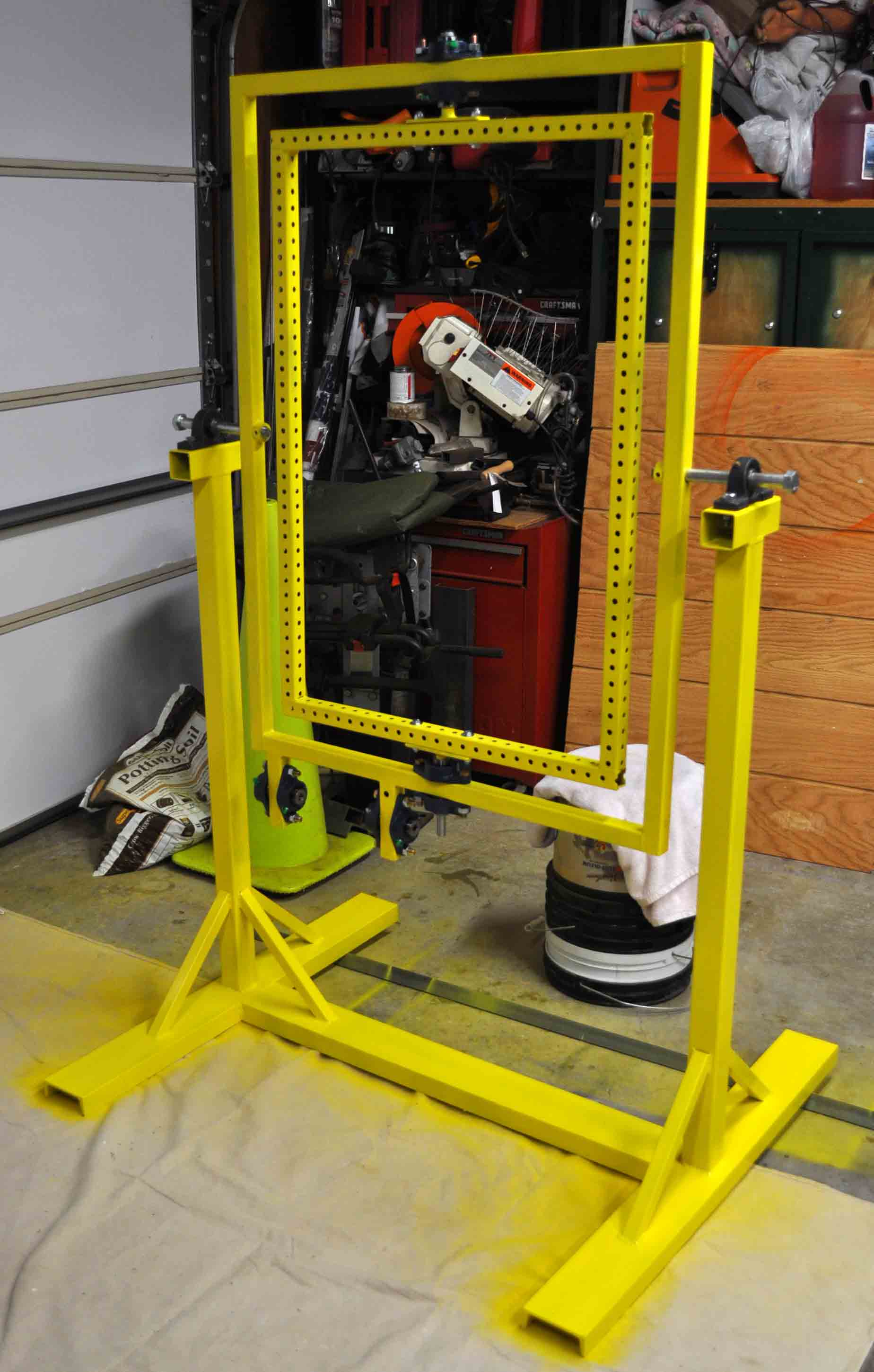
Time for paint. Saftey Yellow seems like the right color for wirling metal. Besides it seems like I am always painting everything flat black to hide the halloween stuff in the dark. |
 |
 |
| With the paint dry to the touch, this is the first test assembly so that I can get some final measurements for gear shafts and chain. Along with find any problems for fixing before final assembly. |
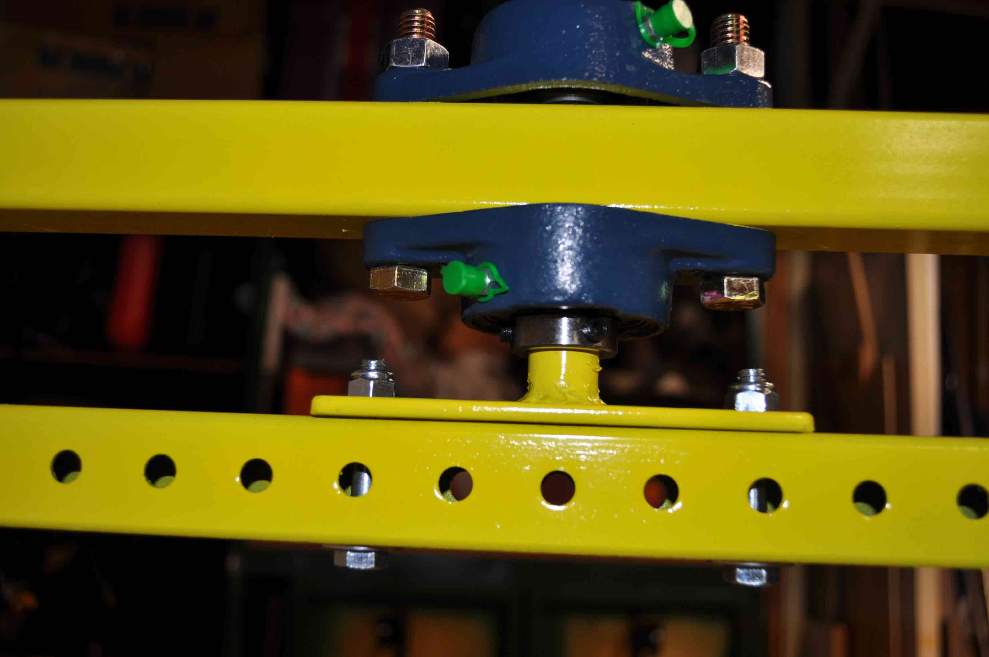
Closeup of the inner ring mount and bearings |
 |
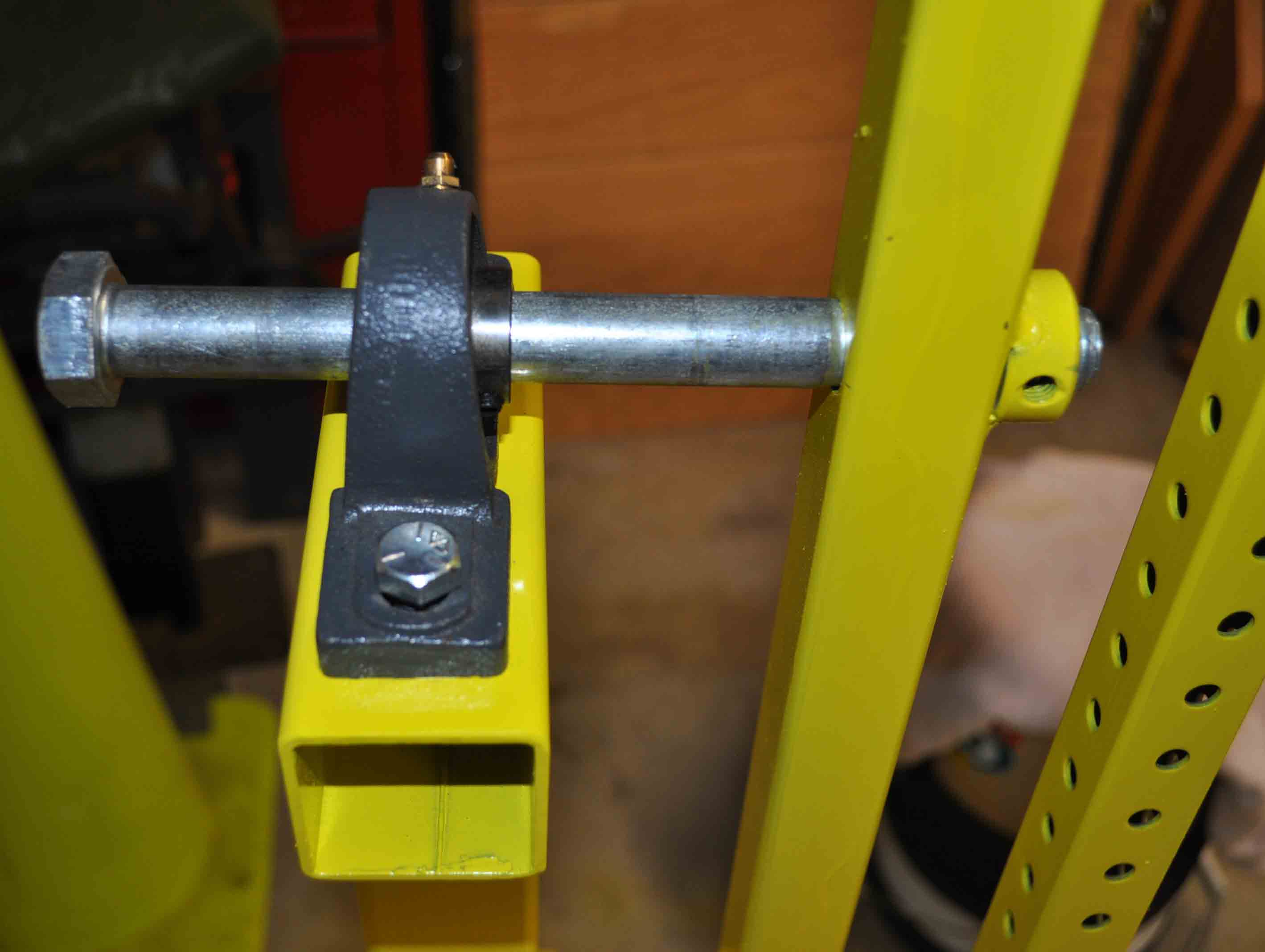 |
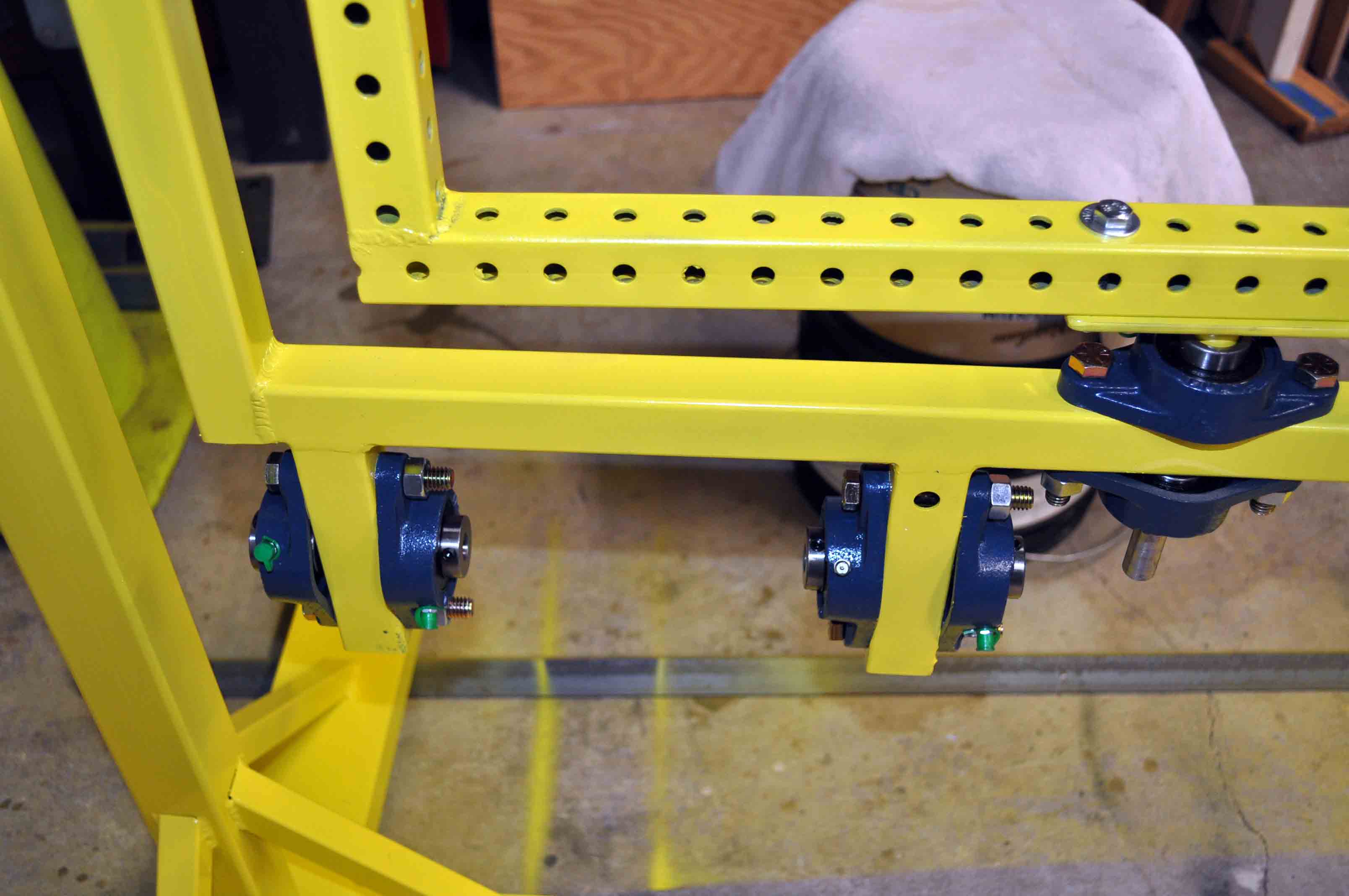
| Closeup of the inner ring drive shaft bearings and mounts |
found that the 3/4 inch bar I had for these pins was not exactly round so some extra bolts from a bin will work for this fit test. Anyway with everything assembled I gave everything a good spin by hand and noticed some wobble from this joint. While it could be fine and likly related to the loose fit of the bolts compared to the final pins that will be secured, I am going to make a change at this point to add a second bearing to each side to add more support. Idealy I would use some 3 inch wide tube but with everything welded up I will add an expansion bracket to allow two bearings to fit. |
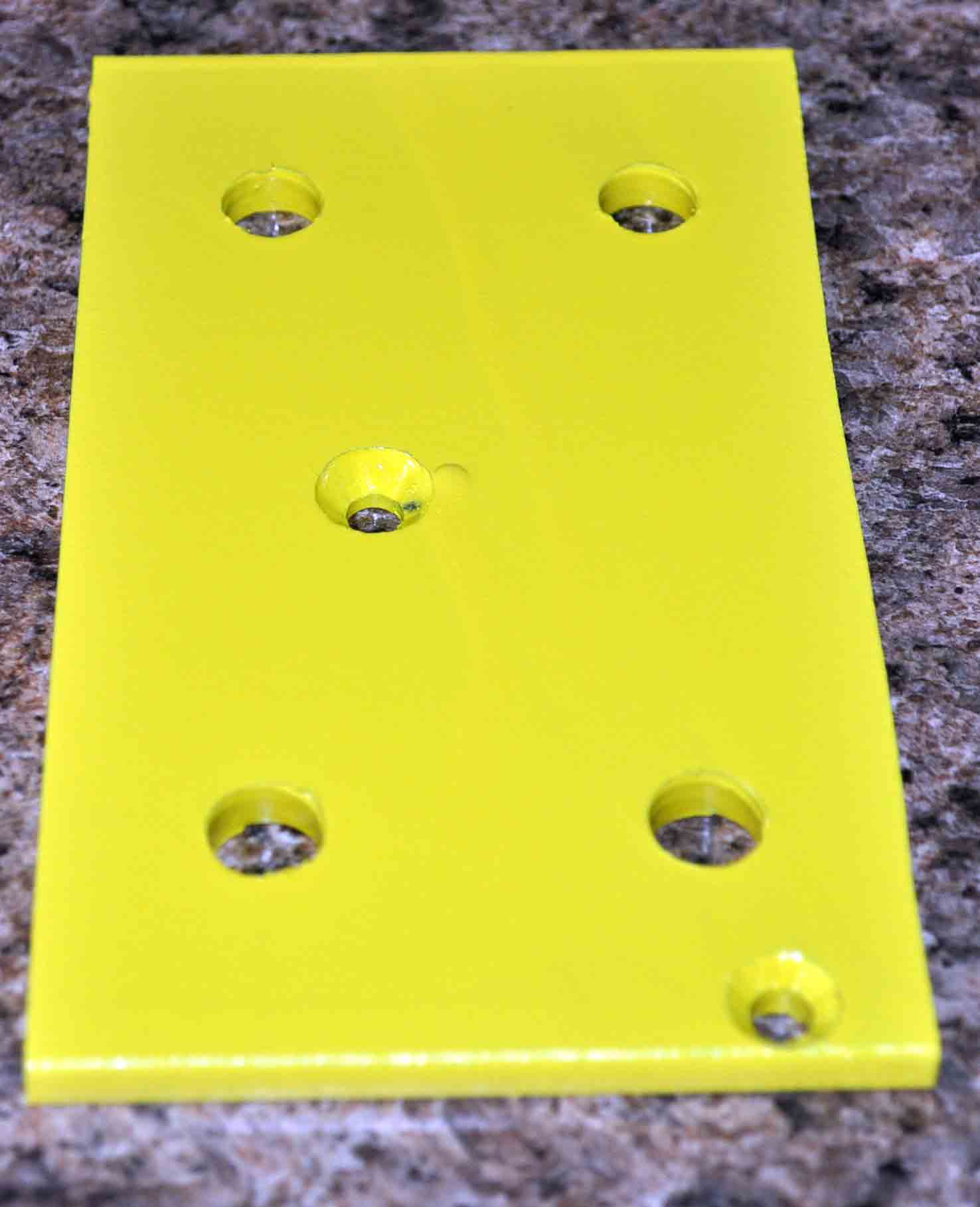 |
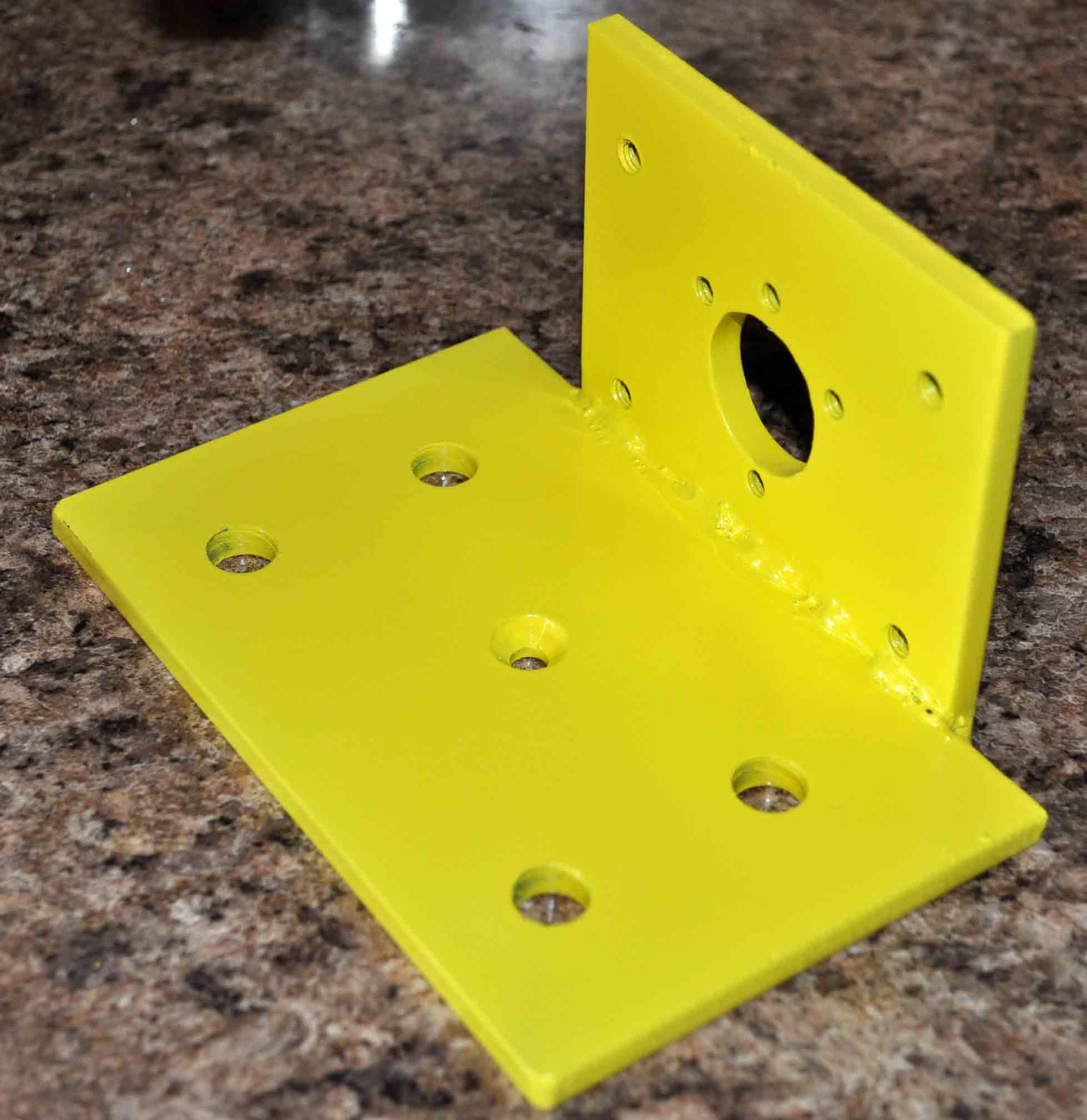 |
| Right side expansion bracket for increasing to two bearings for supporting the main shaft |
Left side expansion bracket for increasing to two bearings for supporting the main shaft. This side includes an additional section for mounting the fixed sprocket that drives the inner ring. |
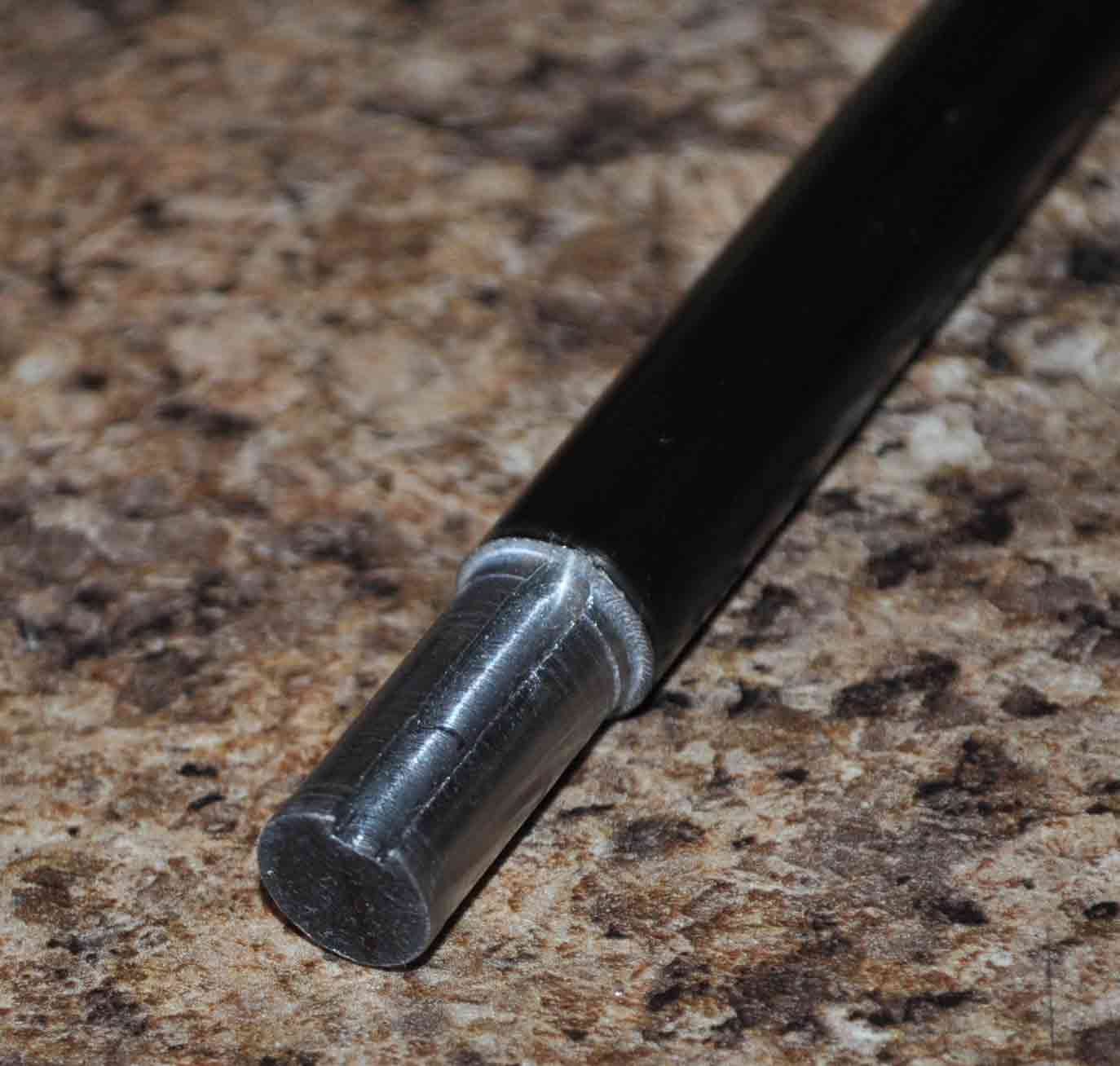 |
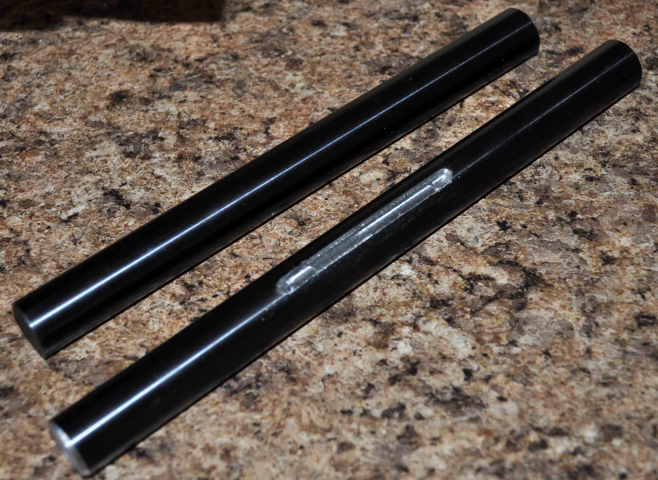 |
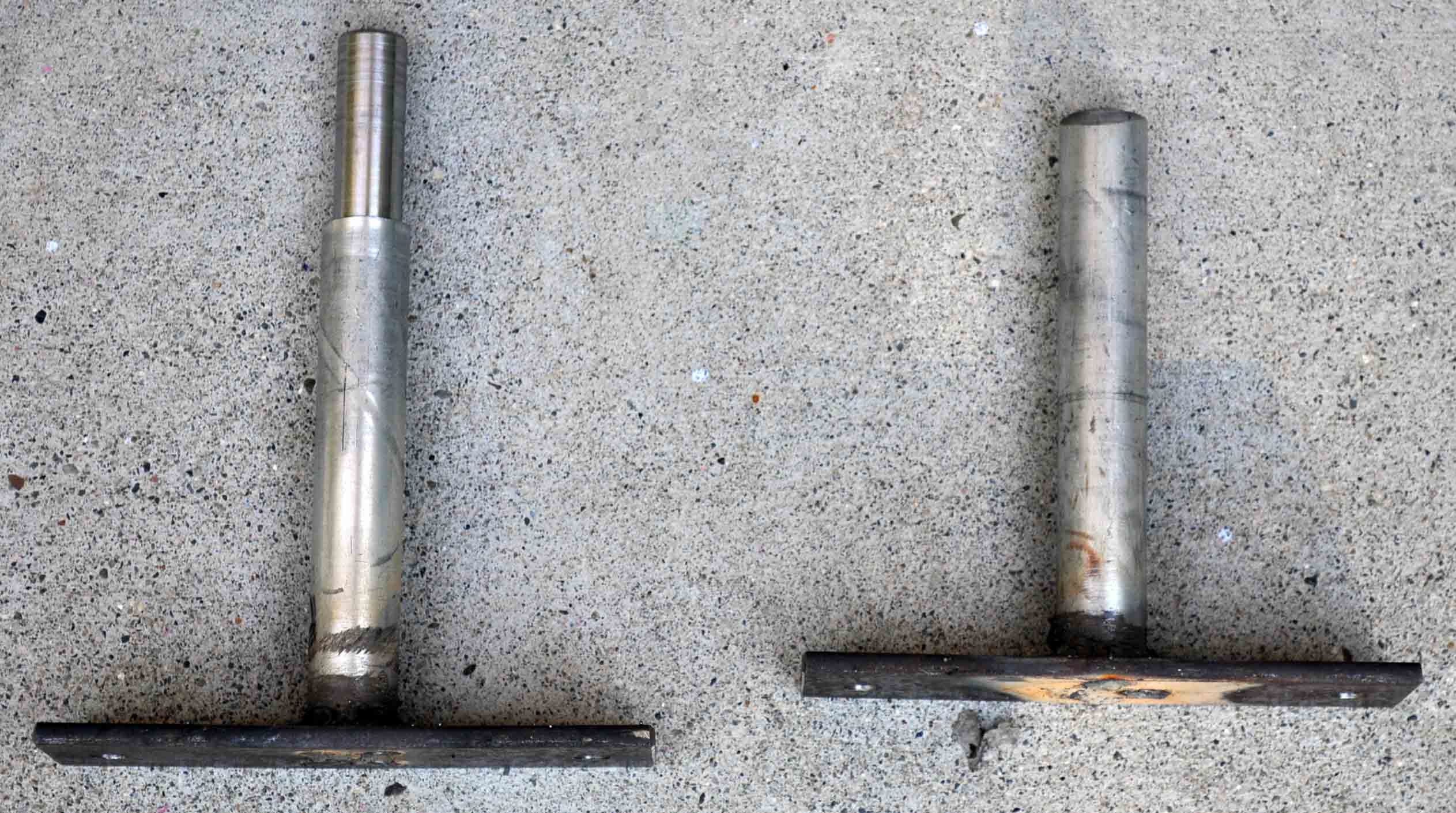
| 1/2 inch drive shaft for inner ring. note that I have turned down the size for press fitting the pinion gear and cut a key way slot. |
3/4 shafts that the outer ring rides on. Note that one has a key way machined into the shaft for the sprocket to be attached |
 |
 |
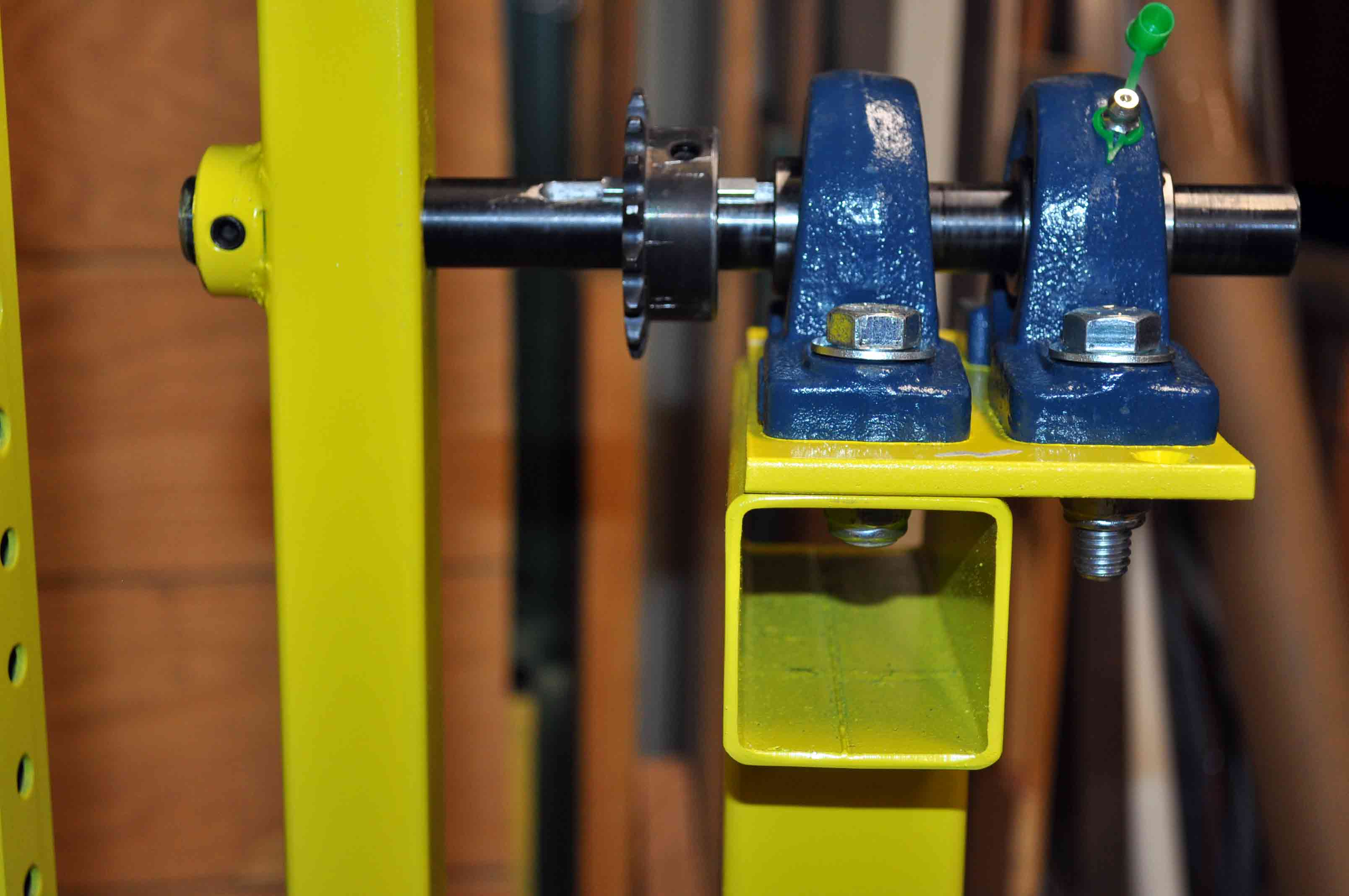
| right side shaft installed with bearings, sprocket and outer ring. I should note here that the 3/4 shaft is press fit into the outer ring will not spin even without the locking screws. |
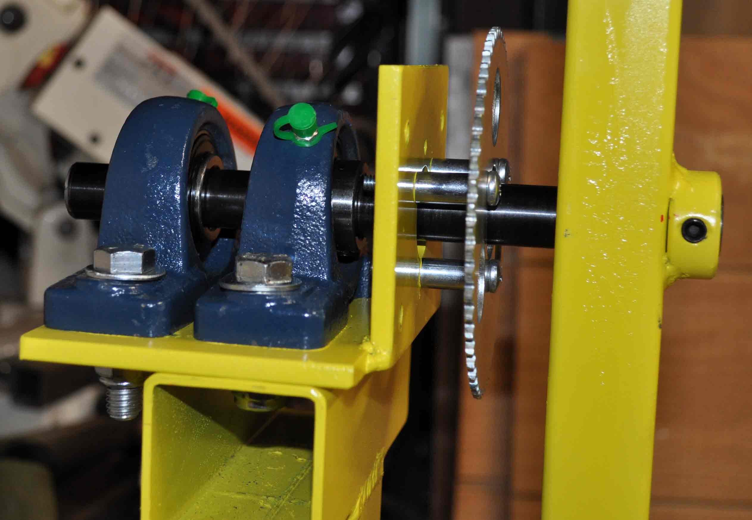
Left side outer ring mount with pillow blocks, smooth shaft and fixed sprocket. Sprocket is held away from the mounting bracket with 3/4 inch spacers and #12 screws. In hind sight 1/4 bolts may have been a better idea here. |
 |
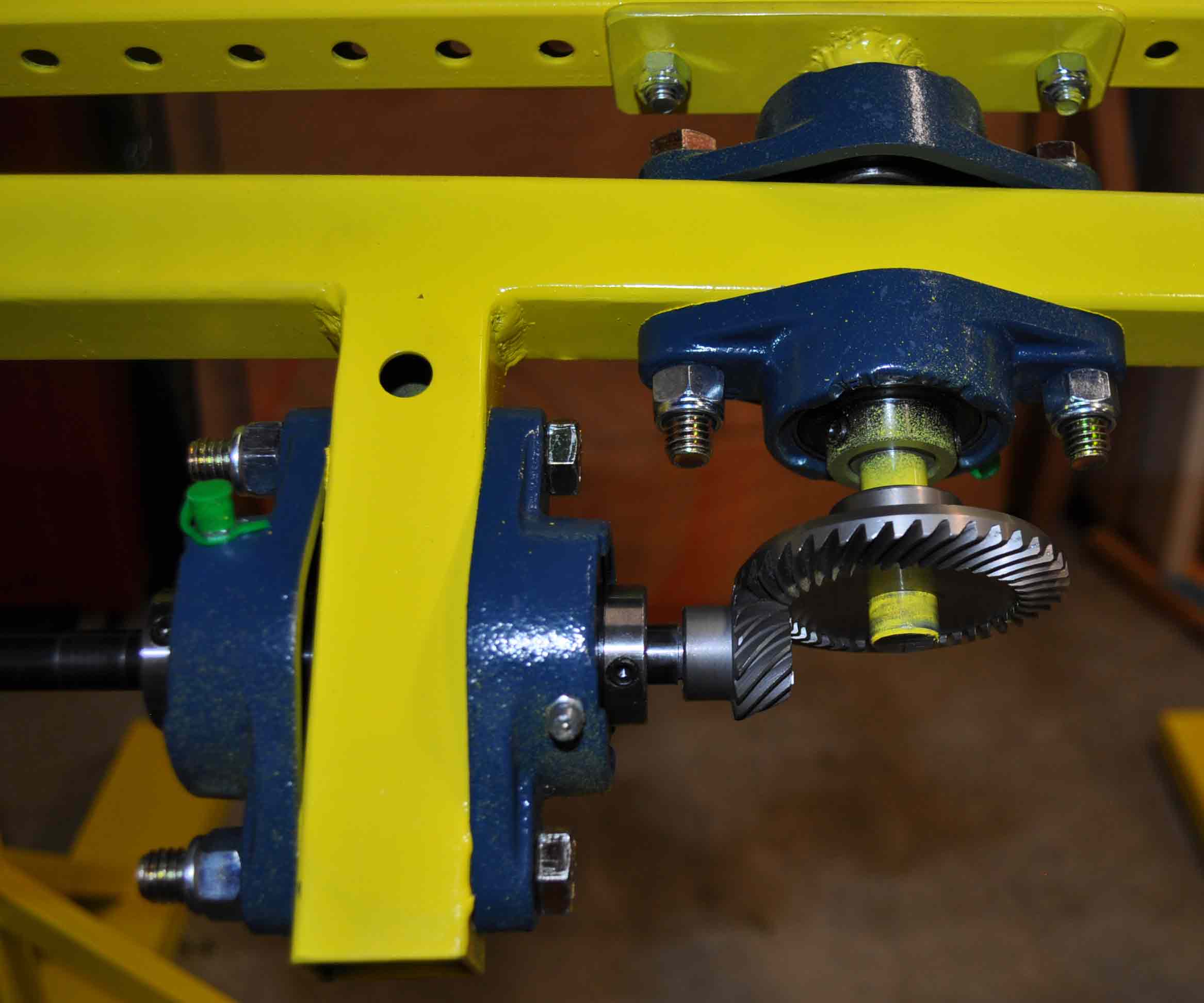 |
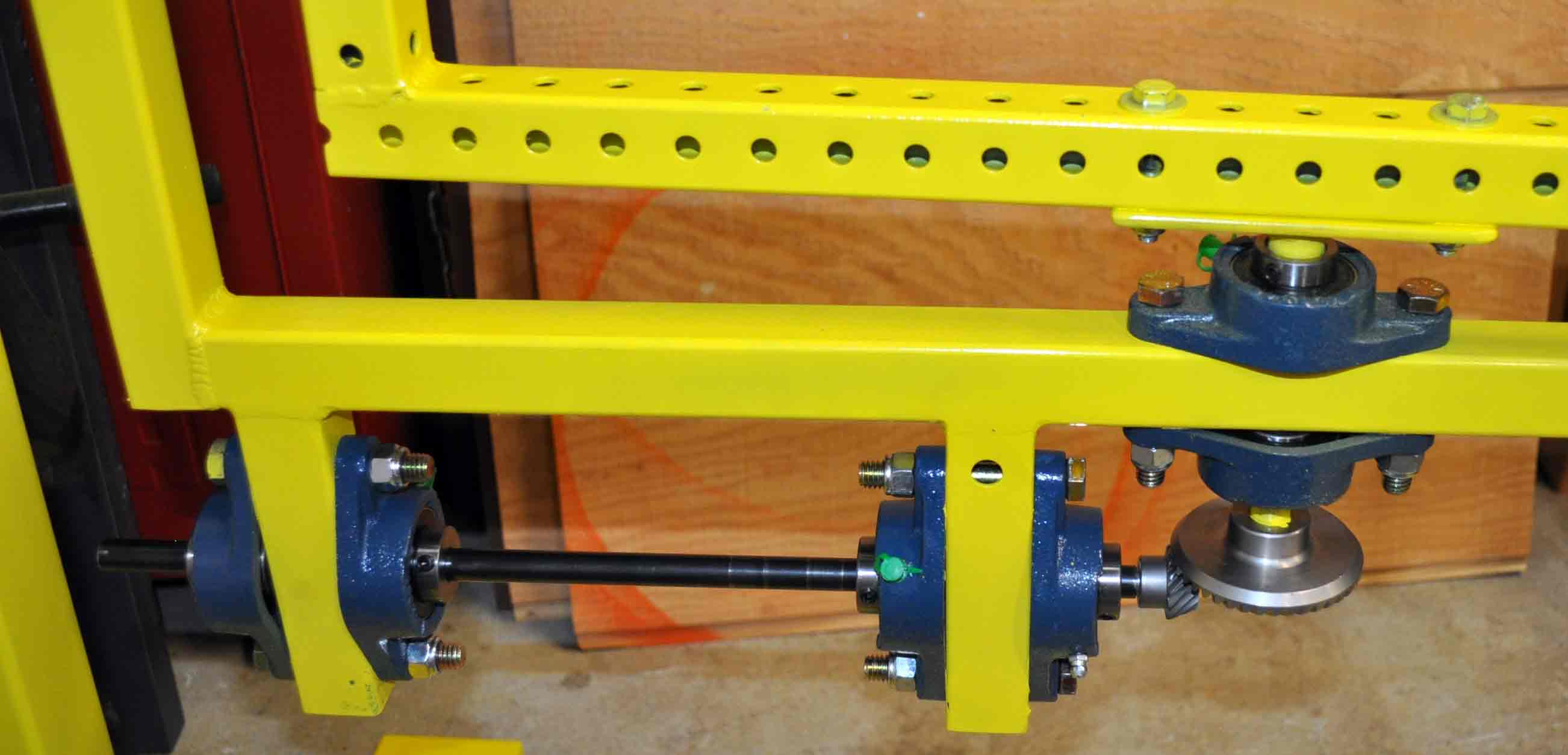
| 1/2 drive shaft installed with gears. |
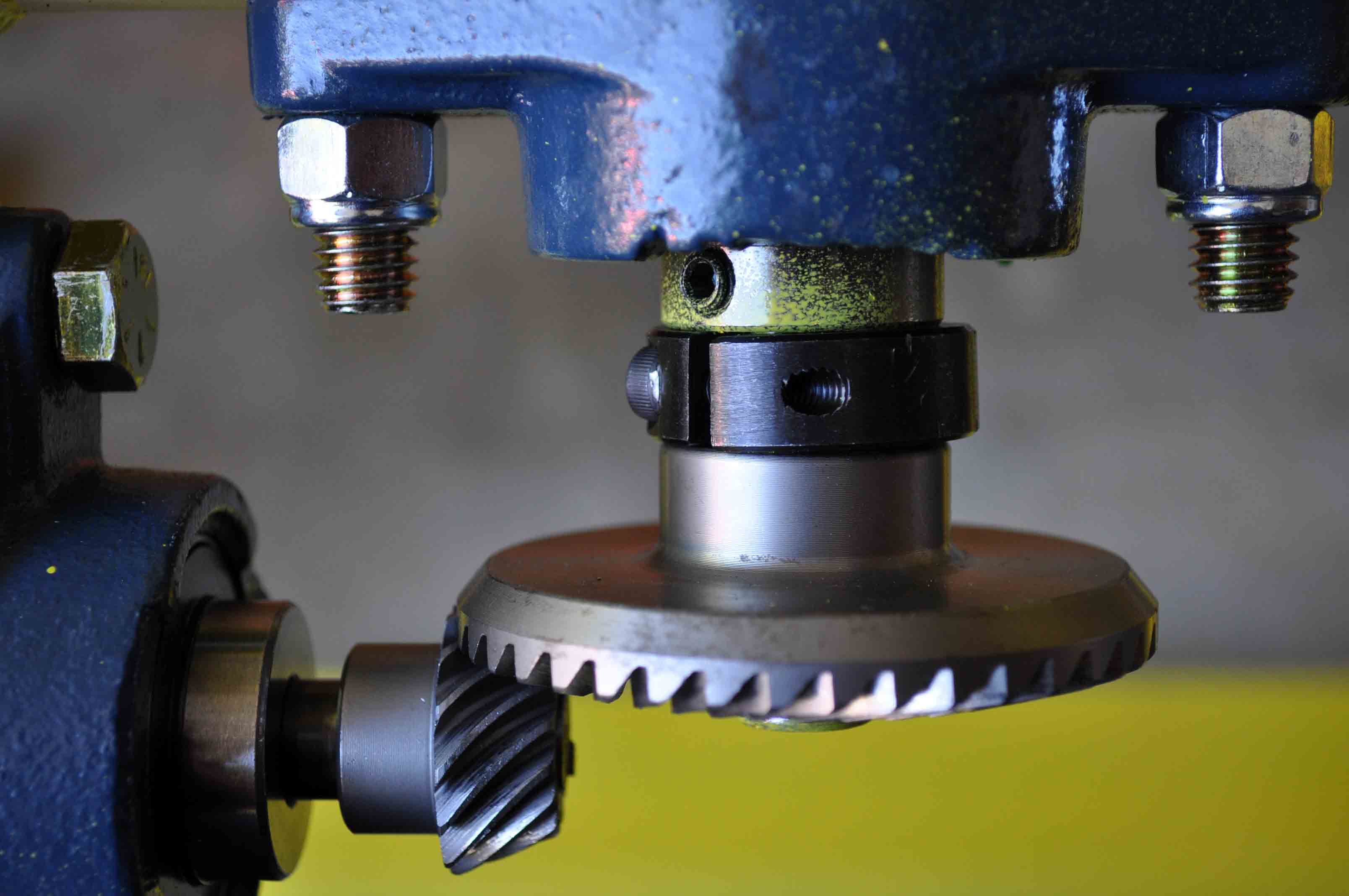
Better view of the bevel gears |
 |
 |
| These bevel gears do not have locking screws and are normally press fit on shafts and held in the correct spacing by a grinders gearbox. However, as I am not using a gear box here I have taken other steps. For the pinion gear the shaft was stepped down and the gear pressed onto the smaller part of the shaft with a keyway that stops any rotation. The step prevents the gear from being driven away from the ring gear. As for the ring gear it is also press fit to the shaft with a keyway to prevent spinning. But in this case the shaft does not have a step that prevents the ring gear from being pushed away from the pinion, so a spacer has been added the shaft forcing the ring gear to stay in place. |
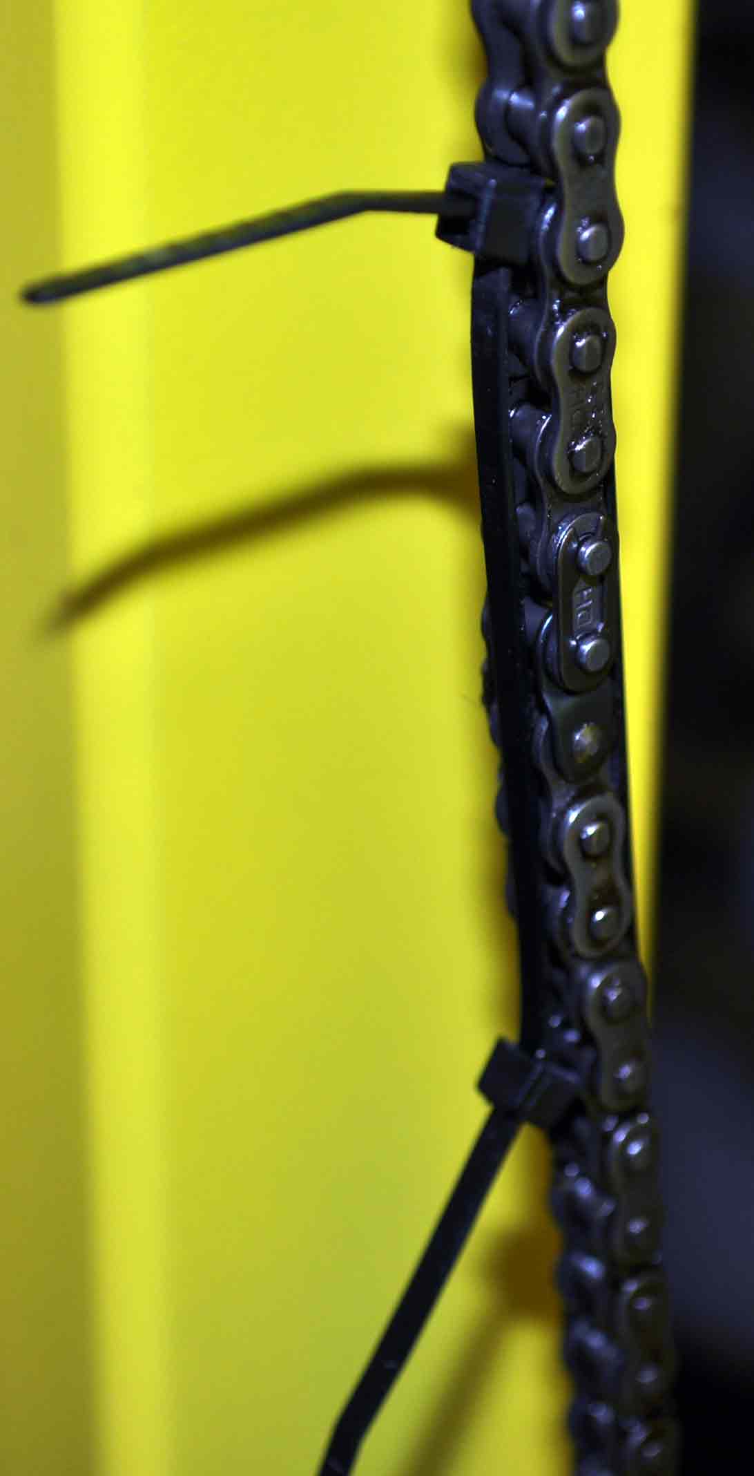
I do not have a tool for stretching chain, so to tighten the chain and get the ends together so I could add the connecting link I used two zip ties to tension the chain. |
 |
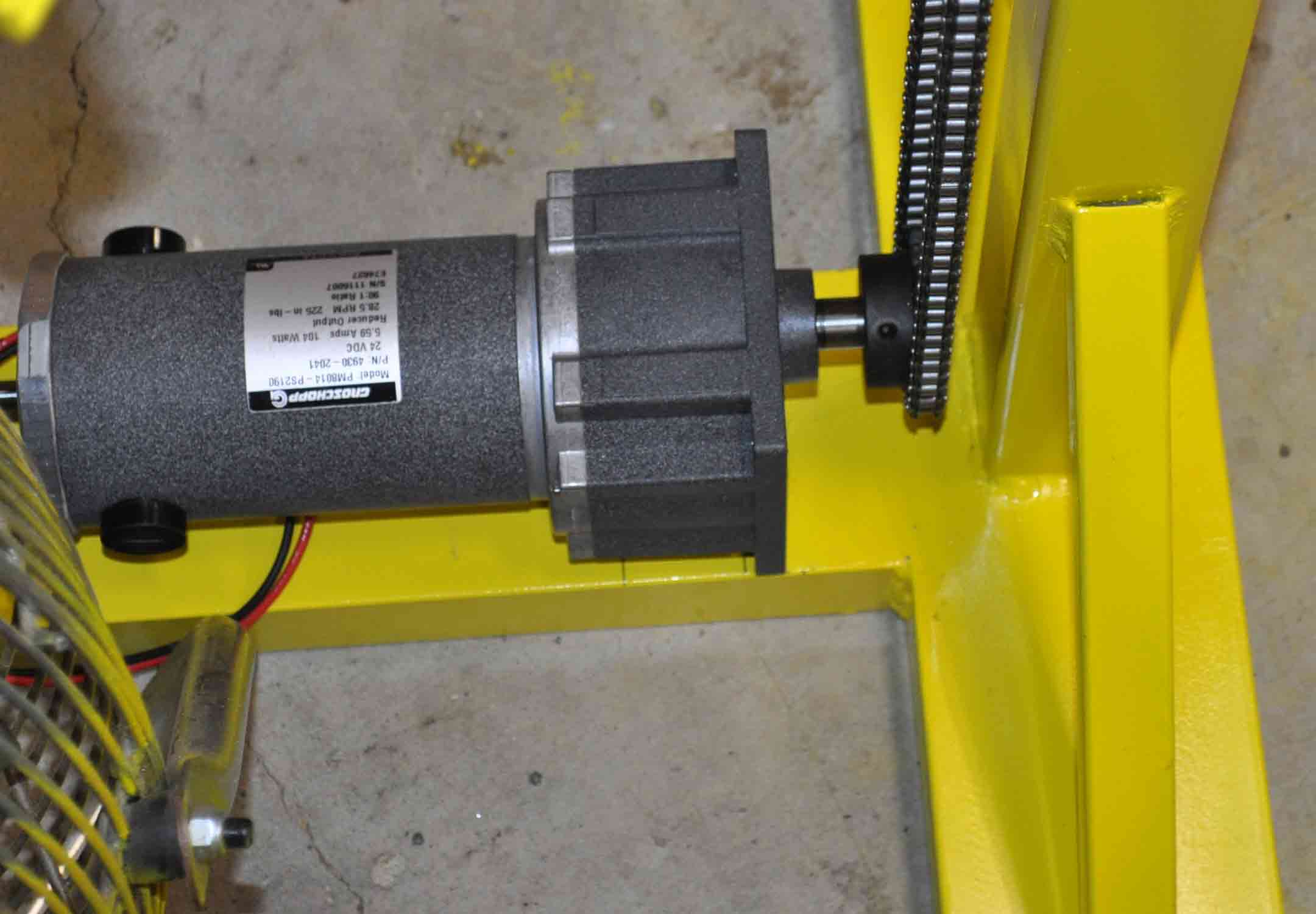 |
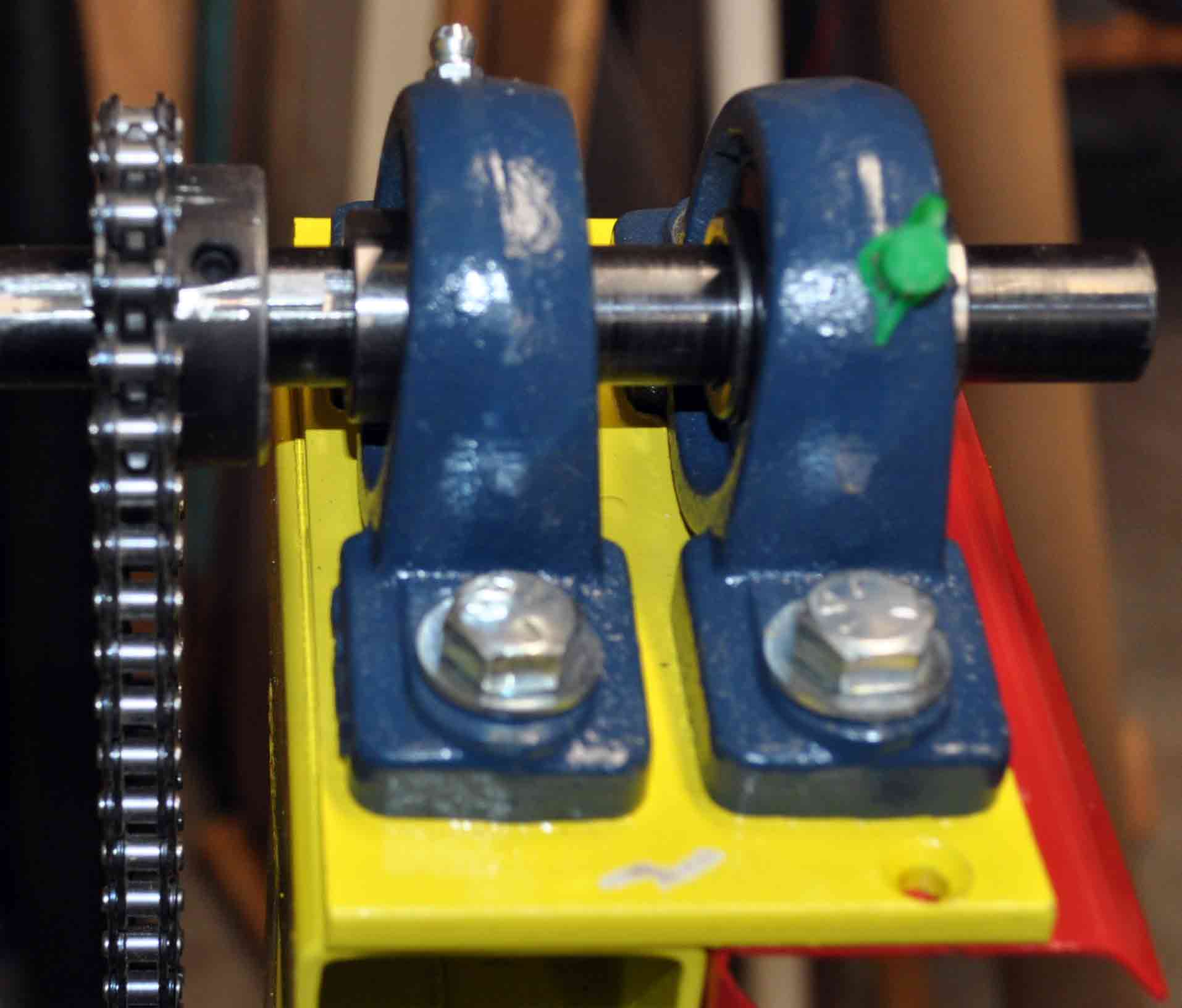
| Though it does not show in the image very well, the important thing here is that the drive gear has been fitted to the shaft with a key to prevent slipage. |
Motor mounded to the base. This was done by placing four holes in the channel and extendig 1/4 inch bolts into the mounting holes of the motor. Specific mounting will be determined by the exact motor that gets used. |
 |
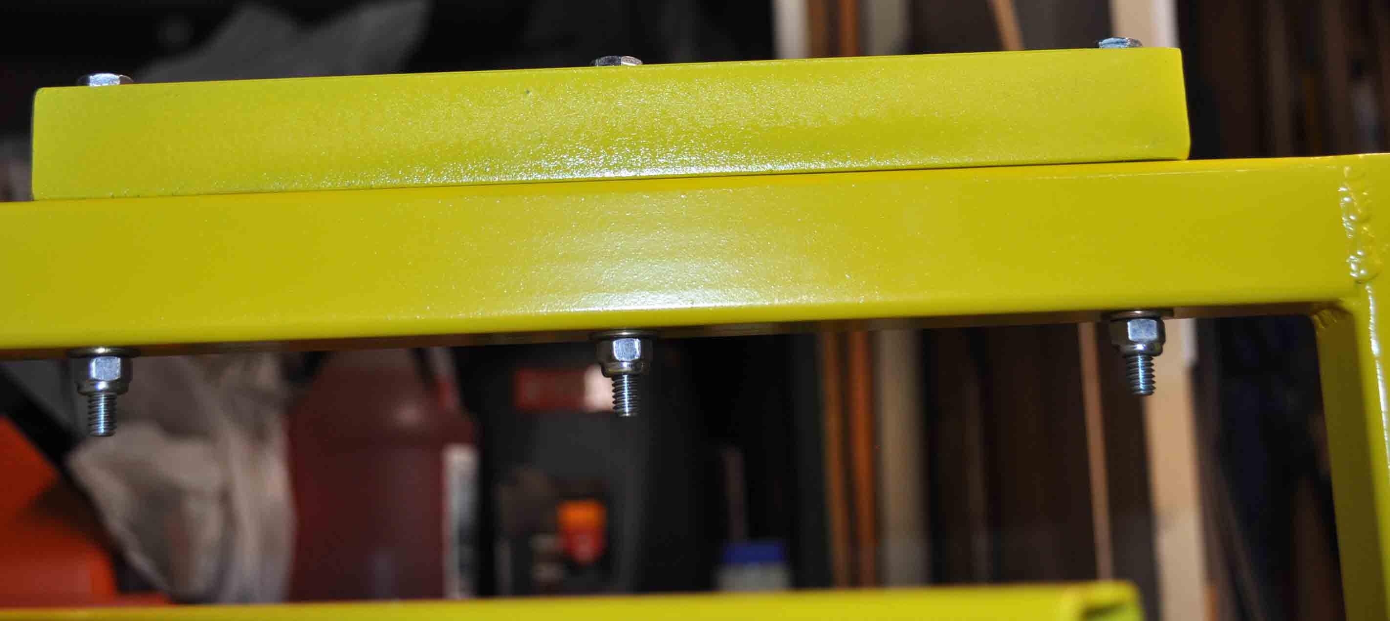 |
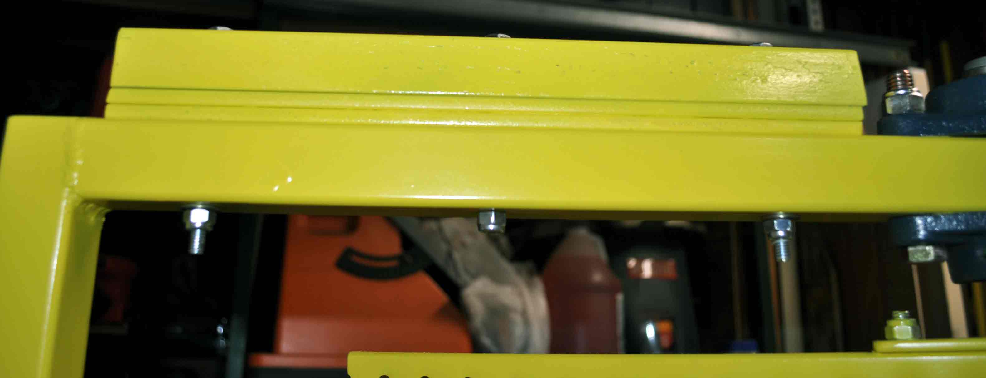
| counter weight to offset the bearings and gears on the other side of the outer frame. I have stacked a bit more weight on the left side of the frame as this the side where most of the inner frame drive system is located |
The counter weights are just solid steel bar that is either 1/4 by 1 1/4 or 1 1/4 square bar. |
  |
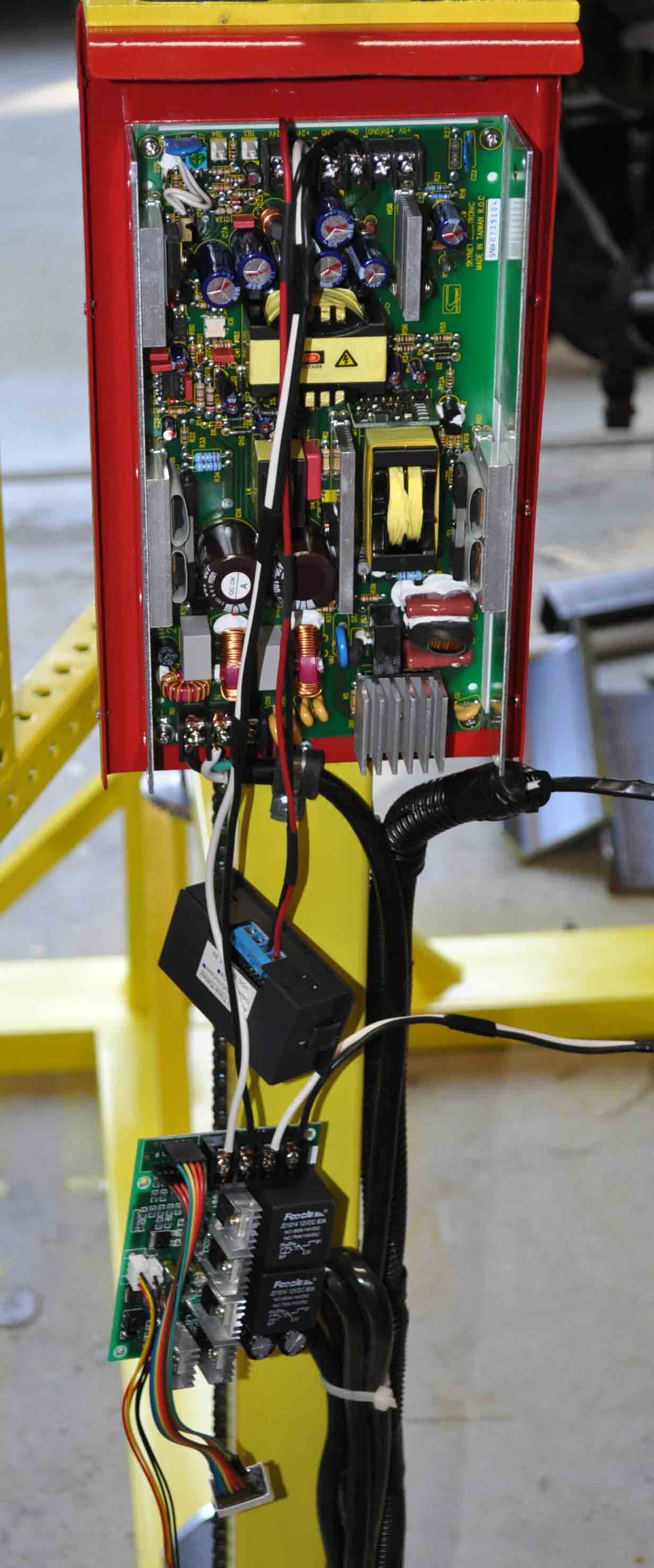 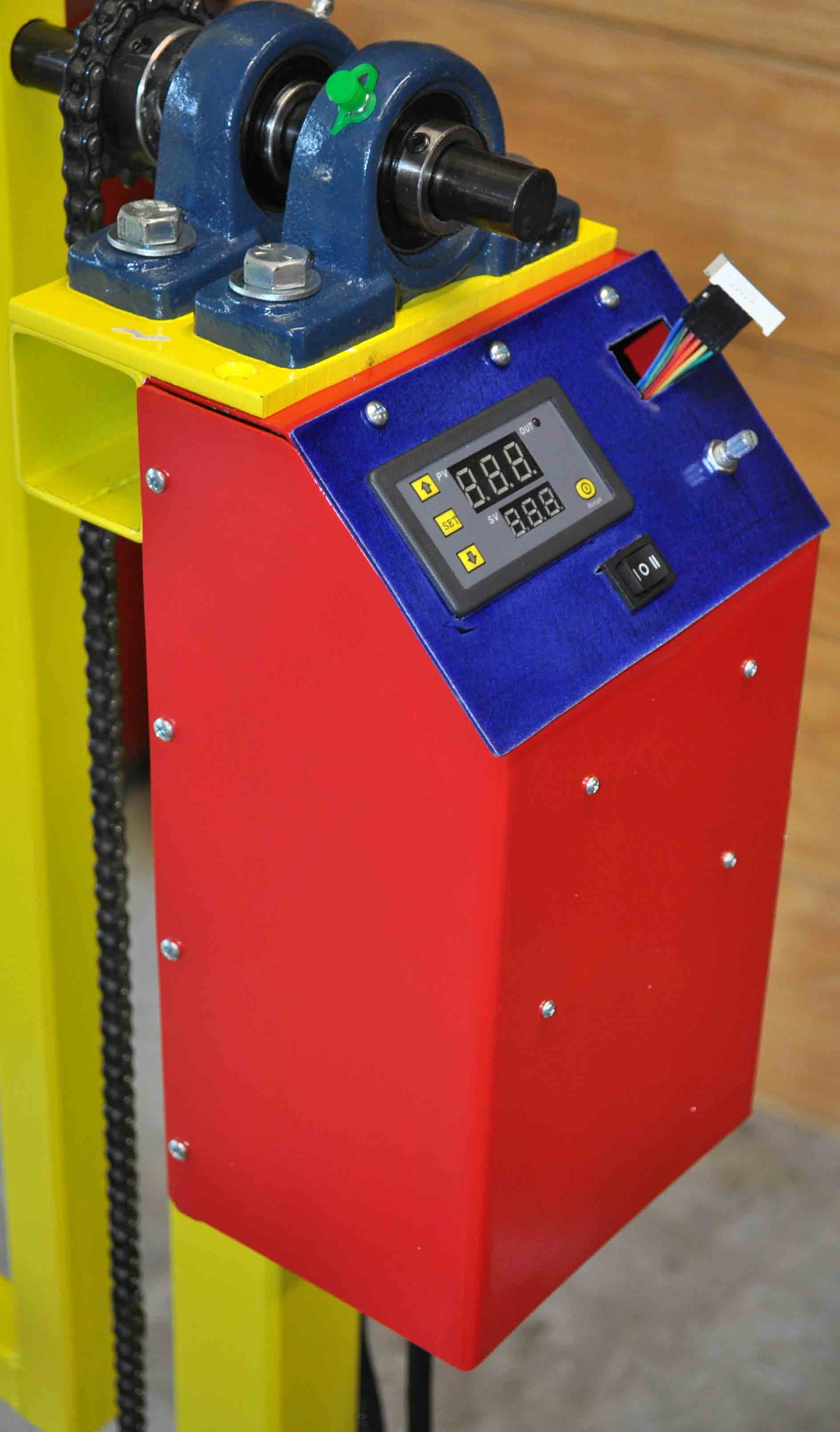 |
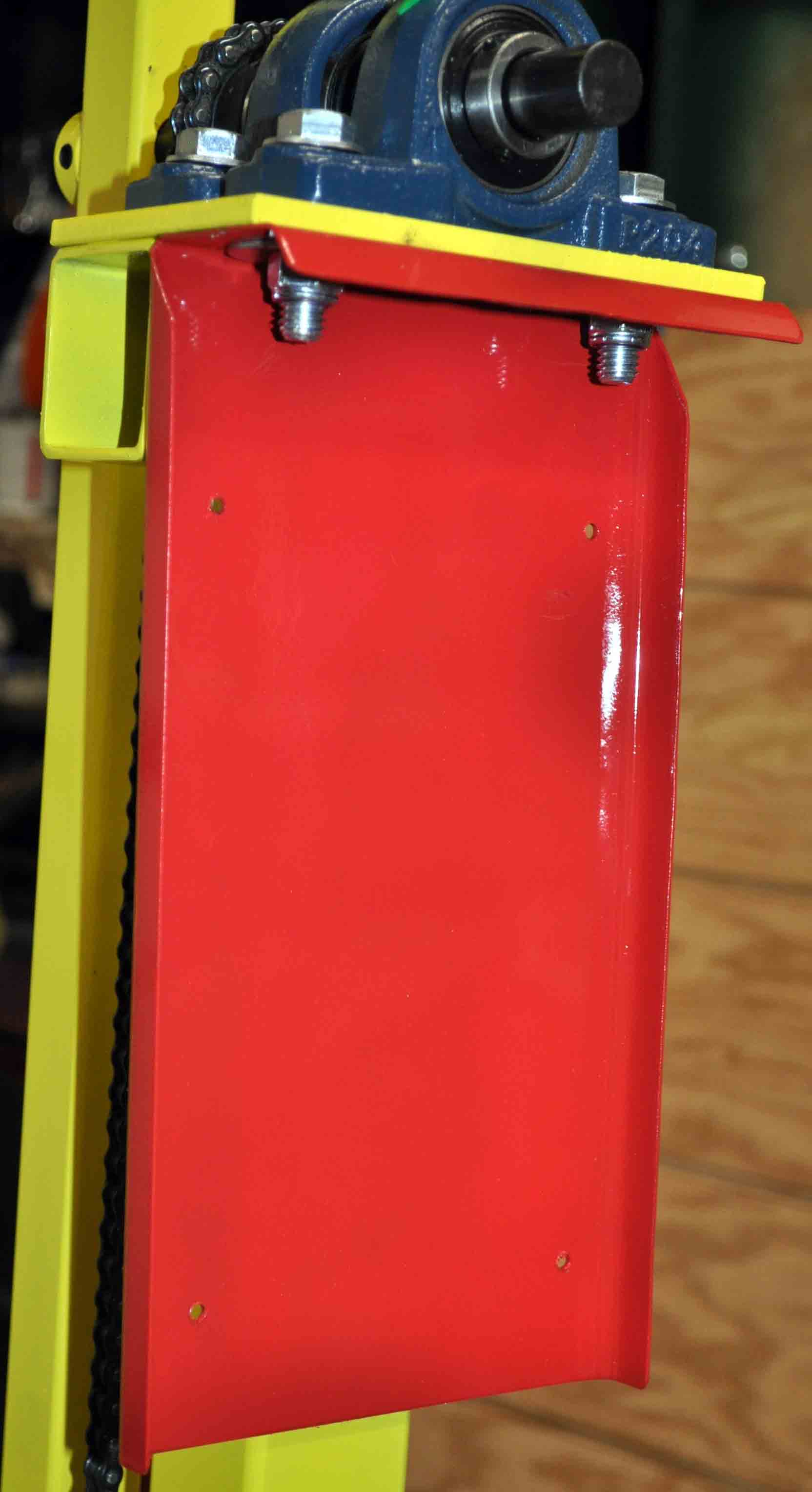
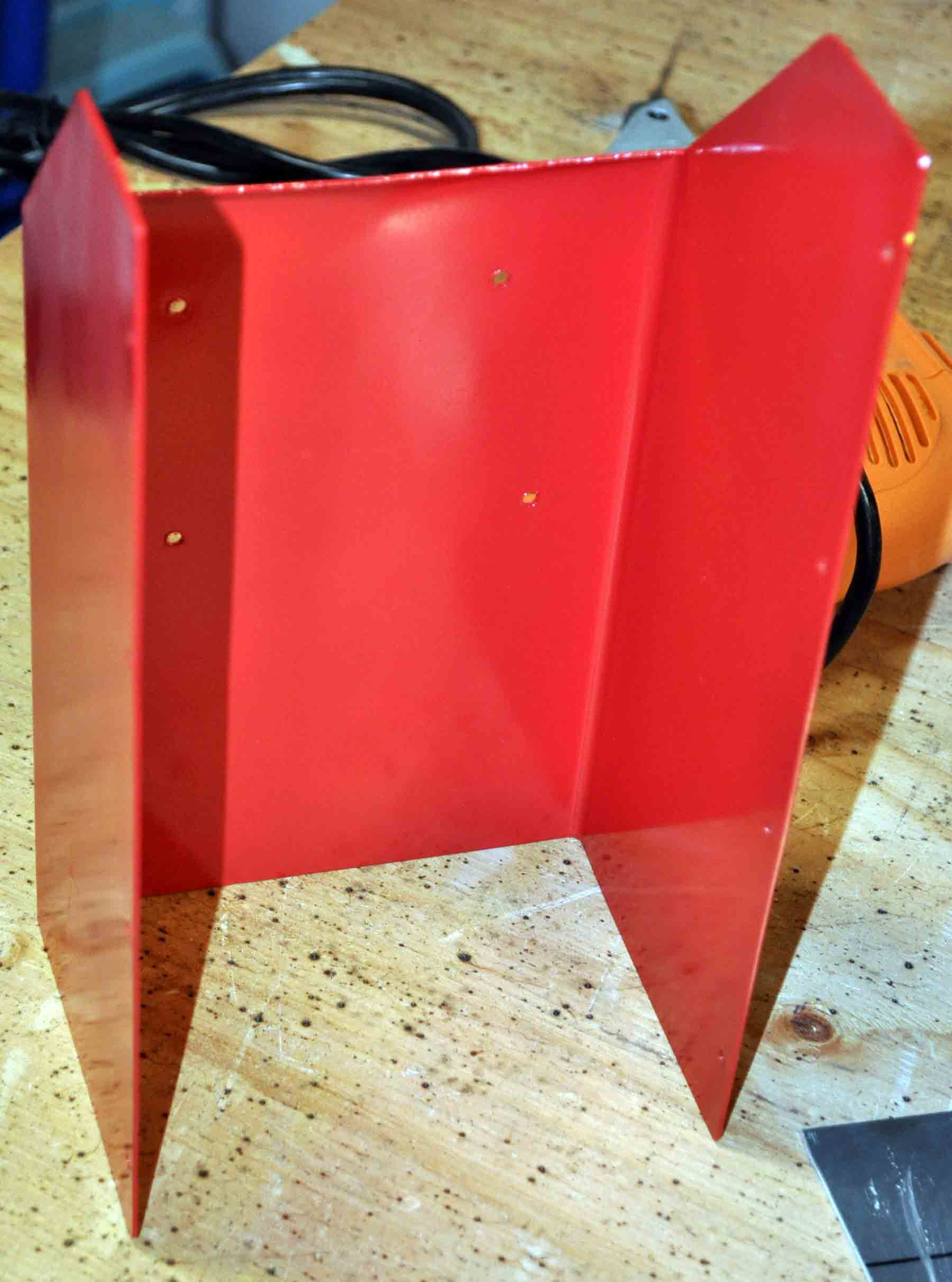
| To hold the electronics and controls I have just bent some 18 ga sheet steel to form a box with an open bottom to help with air flow for cooling and a slanted corner to make working the controls easier. The back of the box mounts using the same bolts for the bearing above. |
Open frame 24 vdc power supply mounted to the rear part of the box along with speed control wired and haning. On the right is the control box assambiled with the face plate installed. The left side of the face plate holds a timer unit where the right side has speed control and speed % readout |
 |
 |
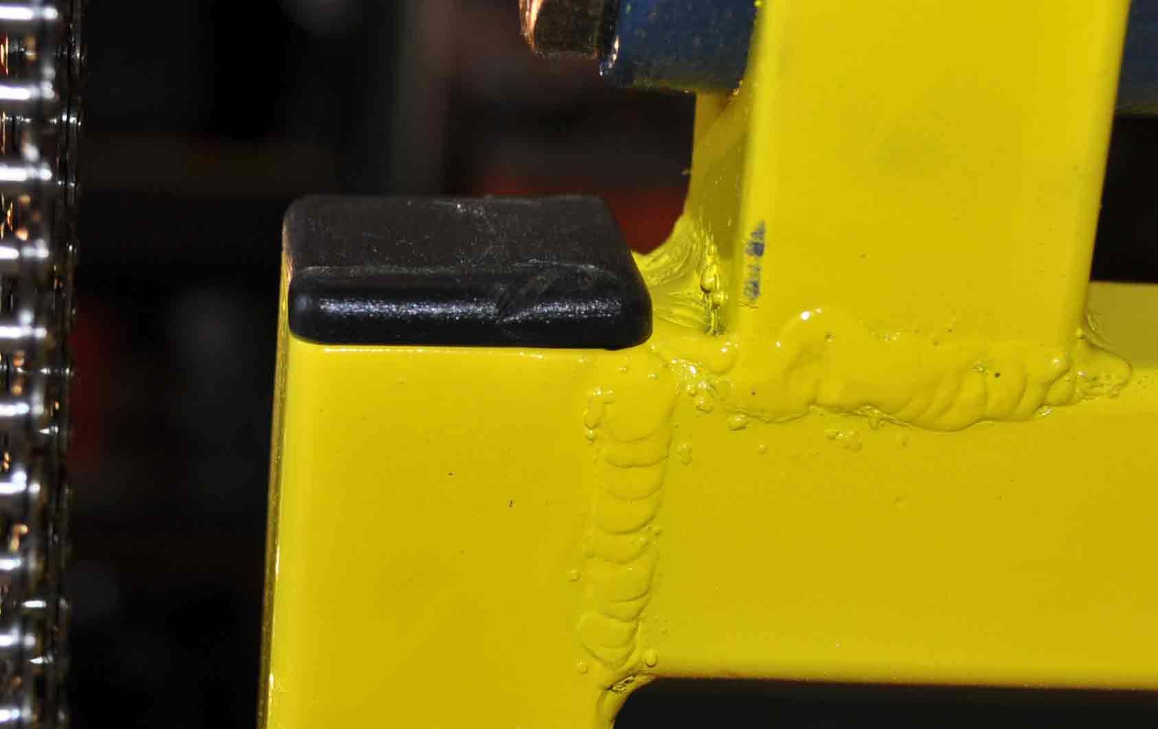 |
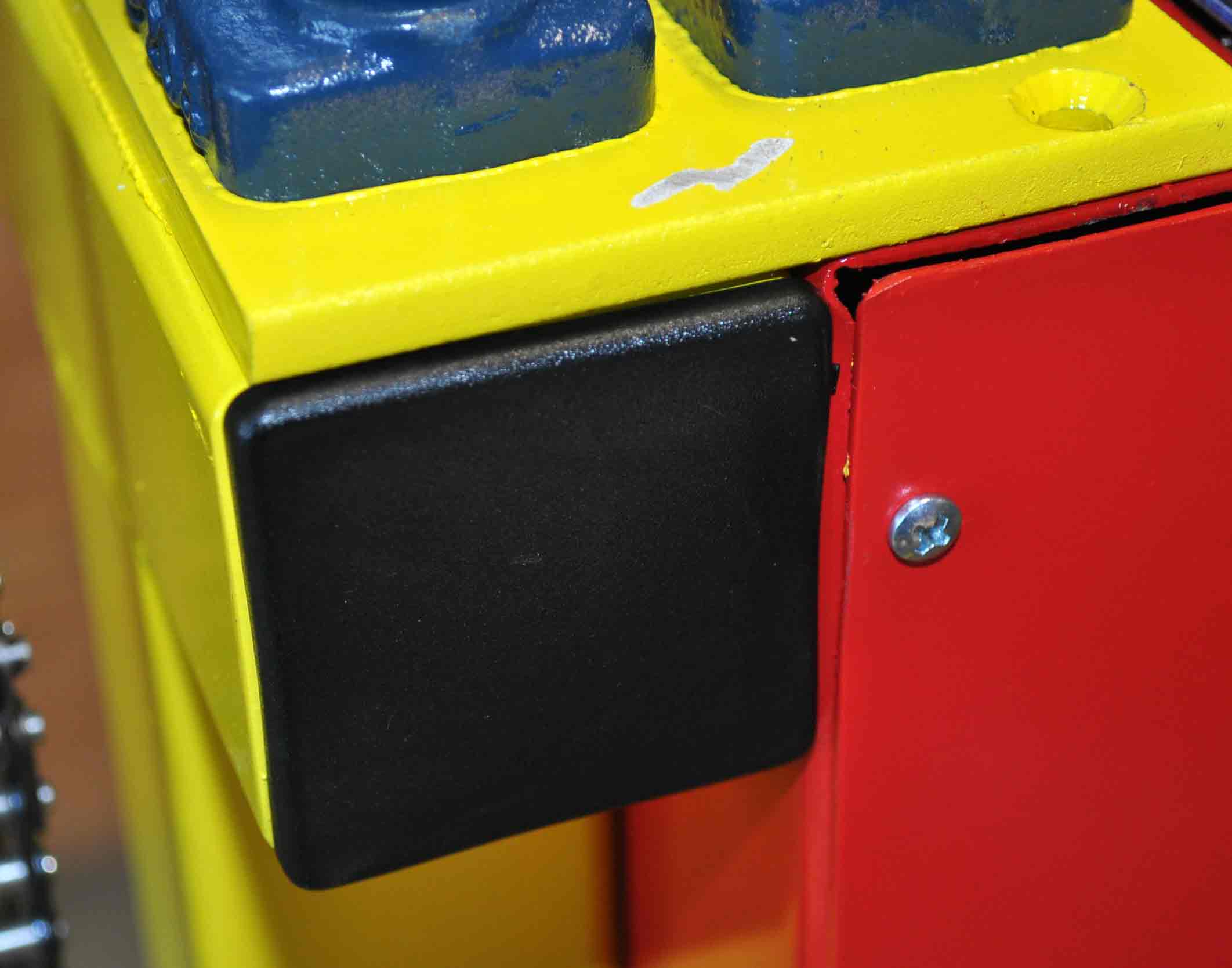
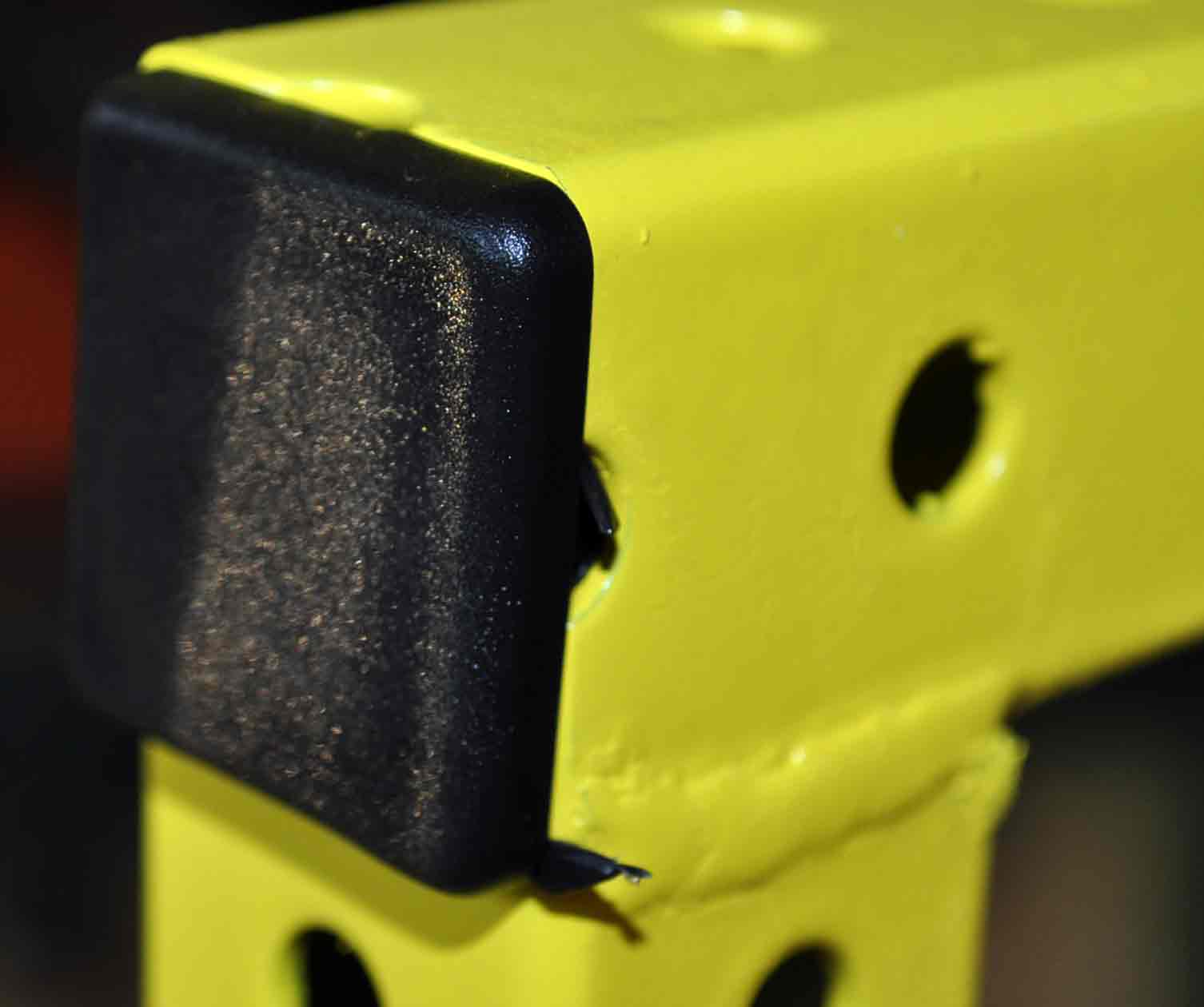
While a bit overkill for something I am just building for myself, I do like a finished look so I have added plastic inserts in to the ends of all the open tubes, but it does look nice. |
 |
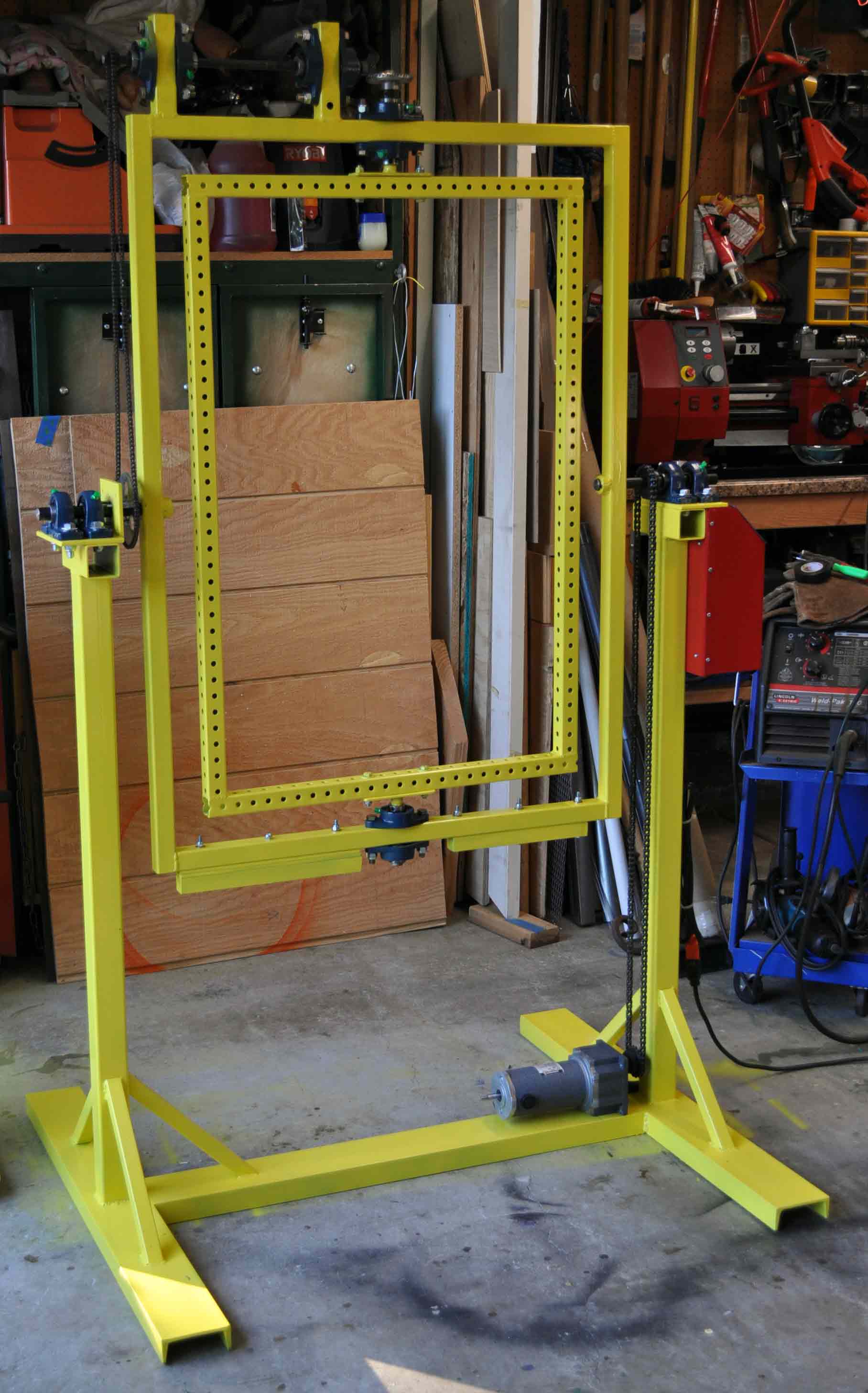 |
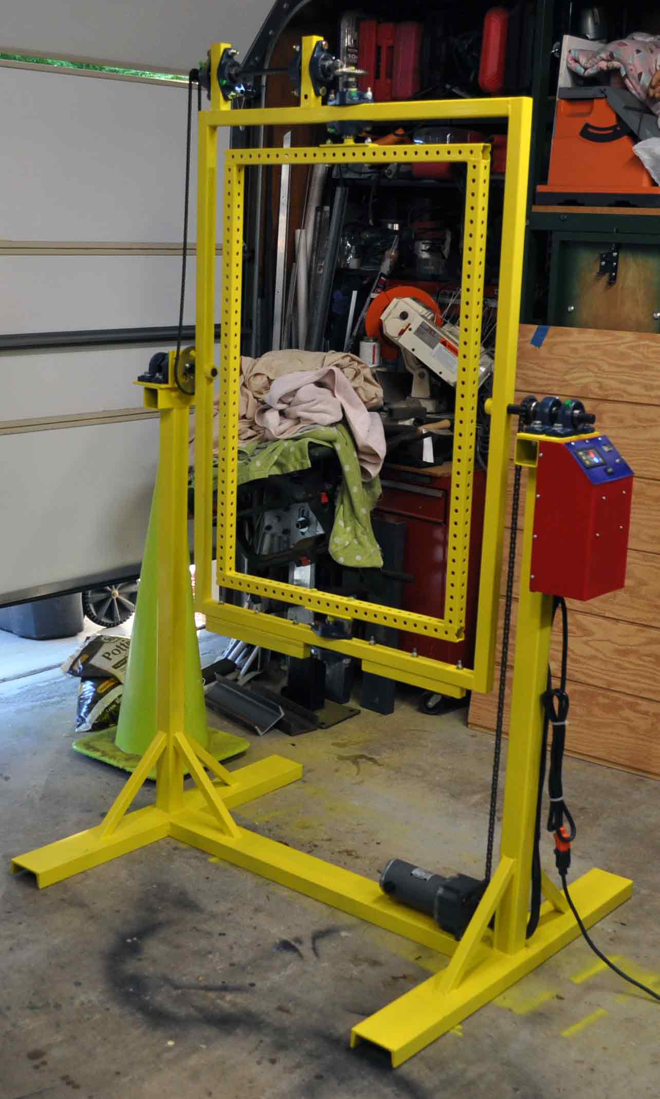
| All wrapped up and ready to cast some hollow parts |


