A friend talked me into trying out the SX family of microcontrollers thinking I would like using them. As 8 bit microcontrollers go it has a fair amount of performance, though you need to realize that the SX family does not have the built in peripherals like that of the PIC or AVR. However if you have been using the Basic Stamp or Prop1 then the programming language is almost a direct match.
To give the SX a workout and fill a need I had at the time I decided to design a cross fader for use in a Peppers Ghost illusion. The cross fader dims one light from fully on to off while at the same time taking a second light from off to fully on. This is accomplished using phase angle control of the AC sin wave, for more information on this take a look at the midi dimmer project. The triggering of a fade is done by switching an input pin from high to low of low to high depending on direction. This makes interfacing the cross fader to a different controller (basic stamp or prop1) or switch mat that would be controlling the overall effect very easy. The fade rate is set with a variable resistor and has a scale of 1 to 30 seconds. This scale can be changed by altering the firmware shown below.
The SX turned out to be a nice device to work with; however I do find that most of my projects have benefited from having a microcontroller with an integrated hardware UART saving my software from having to deal with the sub function of serial communication.
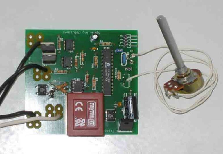
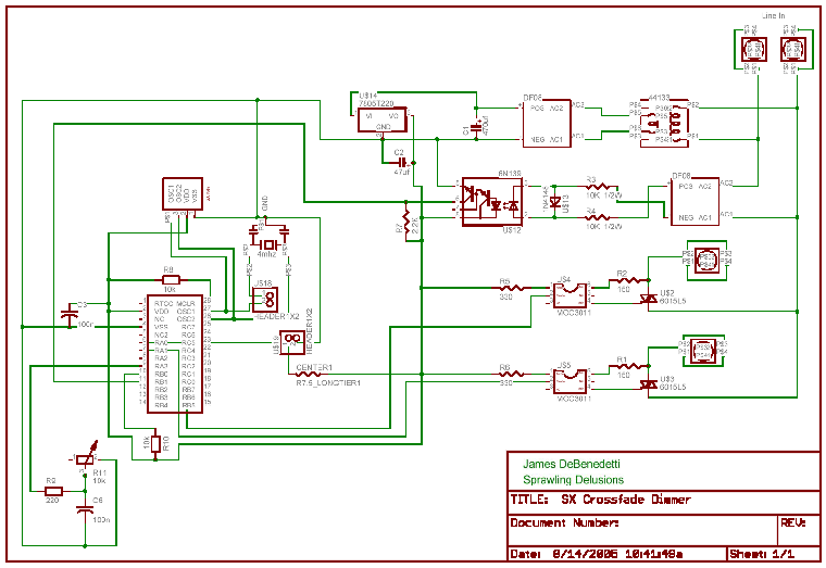
Additionally I have included the schematic, SX/B code, and an image of the project to allow anyone to build this project. And if you are so inclined you can also use this project as a road map to create a light dimmer that you can control via any microcontroller. Please always use caution when working with high voltages
One thing to note is this initial hardware design had one flaw with the resistors in the zero cross detector. This can be seen in the image of the pcb where the two resistors are crossed over each other next to the red transformer.


You can take the below code and paste it directly into the SX/B basic compiler and load it into your sx28 chip
SX/B Source Code:
‘ =========================================================================
‘
‘ File…… PeppersGhostCrossfager4mhz.SXB
‘ Purpose… Fade two lights in diffrent directions to control the lighting effect needed for a peppers gohst
‘ Author…. James DeBenedetti
‘ E-mail….
‘ Started… 7-5-2005
‘ Updated… 8-12-2005
‘
‘ =========================================================================
‘ ————————————————————————-
‘ Program Description
‘ ————————————————————————-
‘Control lighting effect needed to produce a Peppers Ghost effect. Lights are controlled using phase angle control
‘of the normal AC line power found in the United States.
‘Notes:
‘ 1) Initail 16 bit counter was causing to much time to be spent in ISR so an 8 bit counter is now used. The draw back is
‘ a reduction in dim resolution.
‘ 2)
‘ ————————————————————————-
‘ Device Settings
‘ ————————————————————————-
DEVICE SX28, OSCXT2, TURBO, STACKX, OPTIONX
FREQ 4_000_000
‘ ———————————————————————————————————–
‘ IO Pins
‘ ———————————————————————————————————–
Trigger var rc.5 ‘alis name for trigger pin
Light1 var ra.0 ‘alis for light 1 output
Light2 var ra.1 ‘alis for light 2 output
Pot1 var ra.3 ‘alis for Var Resistor
‘ ————————————————————————————————————
‘ Constants
‘ ————————————————————————————————————
maxdimcount con 120 ‘Max count between zero cross
‘ ————————————————————————————————————
‘ Variables
‘ ————————————————————————————————————
countflag var byte ‘Flag to increase index in main loop
PBCheck var byte ‘Temp var to hold ISR Flags
dim_index var byte
Light1level var byte ‘Current dim level count for light 1
light2level var byte ‘Current dim level count for light 2
dimspeed var byte ‘Value read from Var Resistor to scale dim speed
result1 var byte ‘Temp var to hold results from reading var-resistor
result2 var byte
‘ ————————————————————————————————————
INTERRUPT
‘ ————————————————————————————————————
ISR_Start:
‘ ISR code here
PBCheck=WKPND_B ‘Read portB interrupt flags
if PBCheck<>%00000010 then ISR_Exit ‘%00000000 represents port pins. 1=tripped 0=no trip
‘If ISR is not from zerocross then exit ISR
RTCC=0 ‘Reset timer to zero
INC countflag ‘flip countflag to increase count in main loop
ISR_Exit:
WKPND_B=0 ‘Reset portb interrupt flags.
‘Must be done or future interrupts will be skiped
RETURNINT
‘ =========================================================================================
PROGRAM Start
‘ =========================================================================================
Pgm_ID:
DATA “SX/B 1.2 Template”, 0
‘ ———————————————————————————————————-
‘ Program Code
‘ ———————————————————————————————————-
Start:
‘ initialization
TRIS_A = %10000000 ‘ make LED ports outputs
PLP_c = %11011111 ‘set I/O direction
TRIS_c = %10110000
WKPND_B=%00000000 ‘Clear pending flags
WKED_B=%11111101 ‘Set triger edge 1=falling
WKEN_B=%11111001 ‘set I/O direction of port pins 1=output 0=Input
OPTION=$87 ‘Set RTCC prescaler
‘bits PS2, PS1, PS0 of OPTION
‘ 0 0 0 =2 OR $80
‘ 0 0 1 =4
‘ 0 1 0 =8 or $82
‘ 0 1 1 =16 or $83
‘ 1 0 0 =32
‘ 1 0 1 =64 or $85
‘ 1 1 0 =128 OR $86
‘ 1 1 1 =256 OR $87
‘$88=none
‘Read Pot for dim speed Value
HIGH Pot1 ‘charge the capacitor
PAUSEUS 350 ‘for 250 us
RCTIME pot1, 1, result1, 9 ‘measure in 400 us (2 x 200) units
result2=result1
if result2 result2=1
endif
if result2>64 then
result2=120
endif
dimspeed = result2 ‘Load dimspeed, must be at least 1 and not greater than maxdimcount
Main:
‘Move dim_index if flag is greater than threshold
‘base dim index increases one per zero cross
If countflag>dimspeed then
countflag=0
if trigger = 1 then
if dim_index
INC dim_index
else
dim_index=maxdimcount
endif
else
if dim_index>0 then
DEC dim_index
else
dim_index=0
endif
endif
endif
‘Main Loop – Phase Angle Control for Dimming
light1level=dim_index
light2level=maxdimcount-dim_index
‘if RTCC < dimspeed then next1
if RTCC < light1level then next1
light1=0 ‘turn on light 1
next1:
if RTCC < light2level then next2
light2=0 ‘turn on light 2
next2:
if RTCC
light1=1 ‘turn light1 off for zero cross
light2=1 ‘turn light2 off for zero cross
goto next2
GOTO Main
