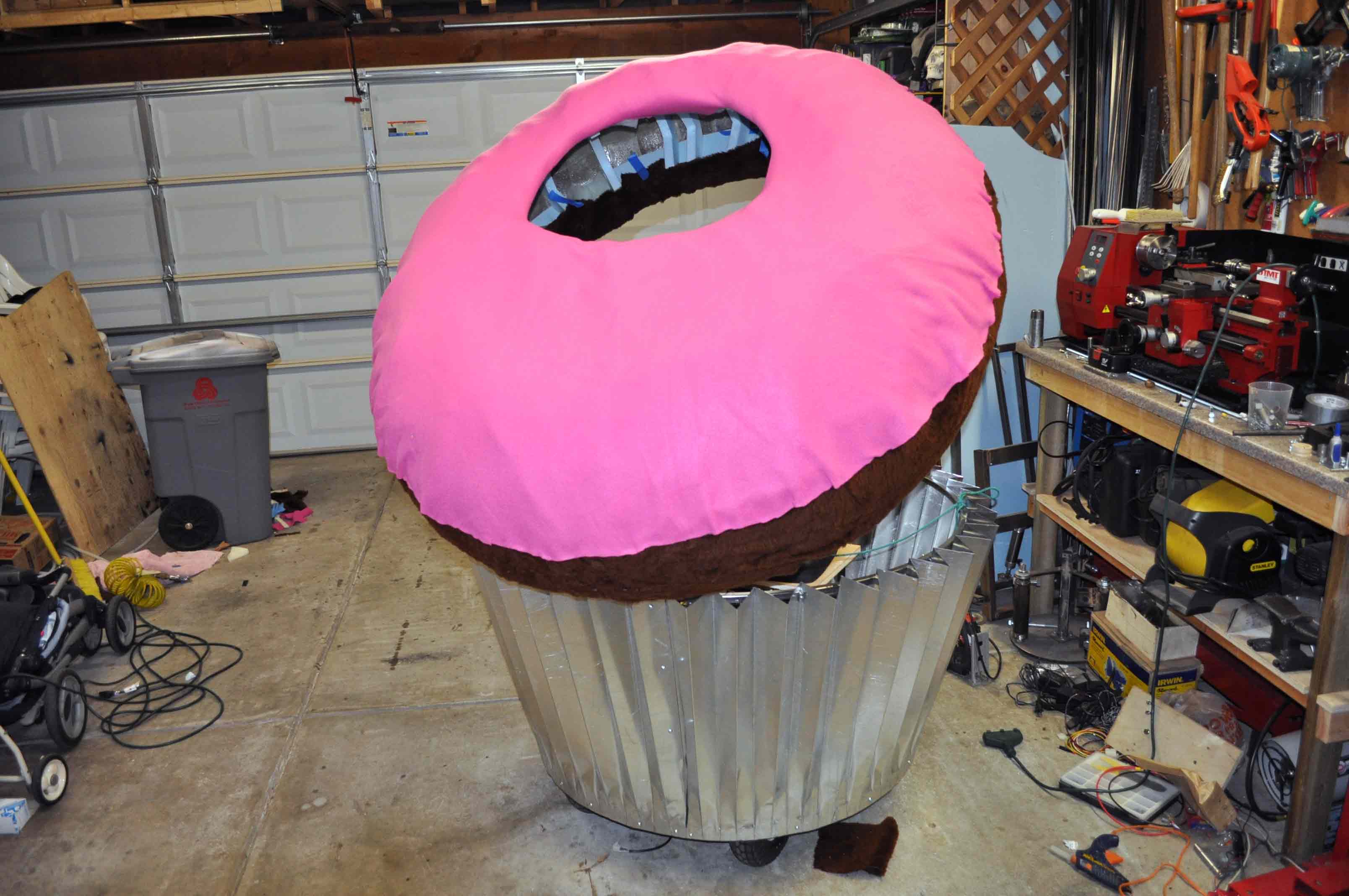
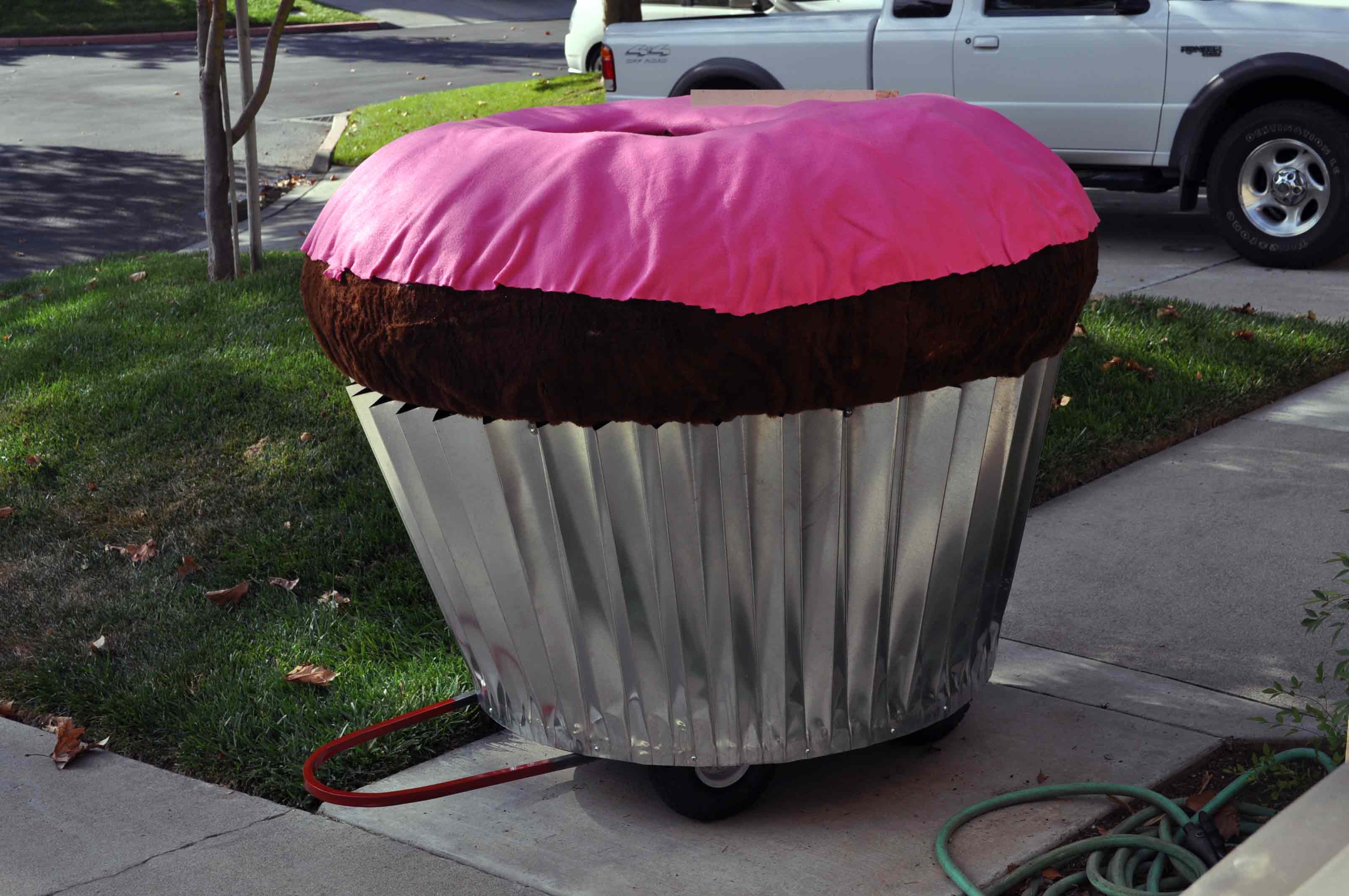
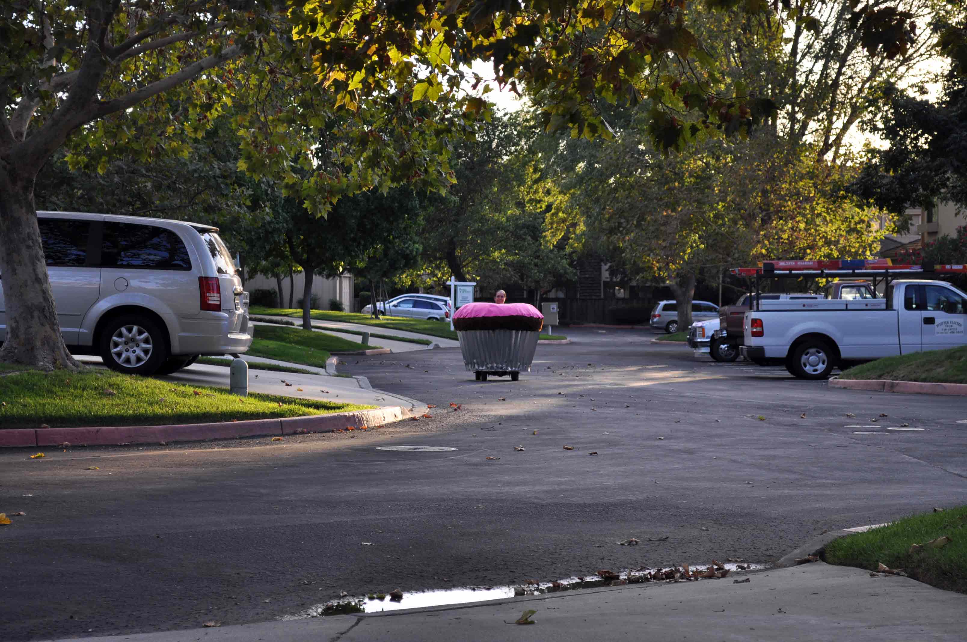
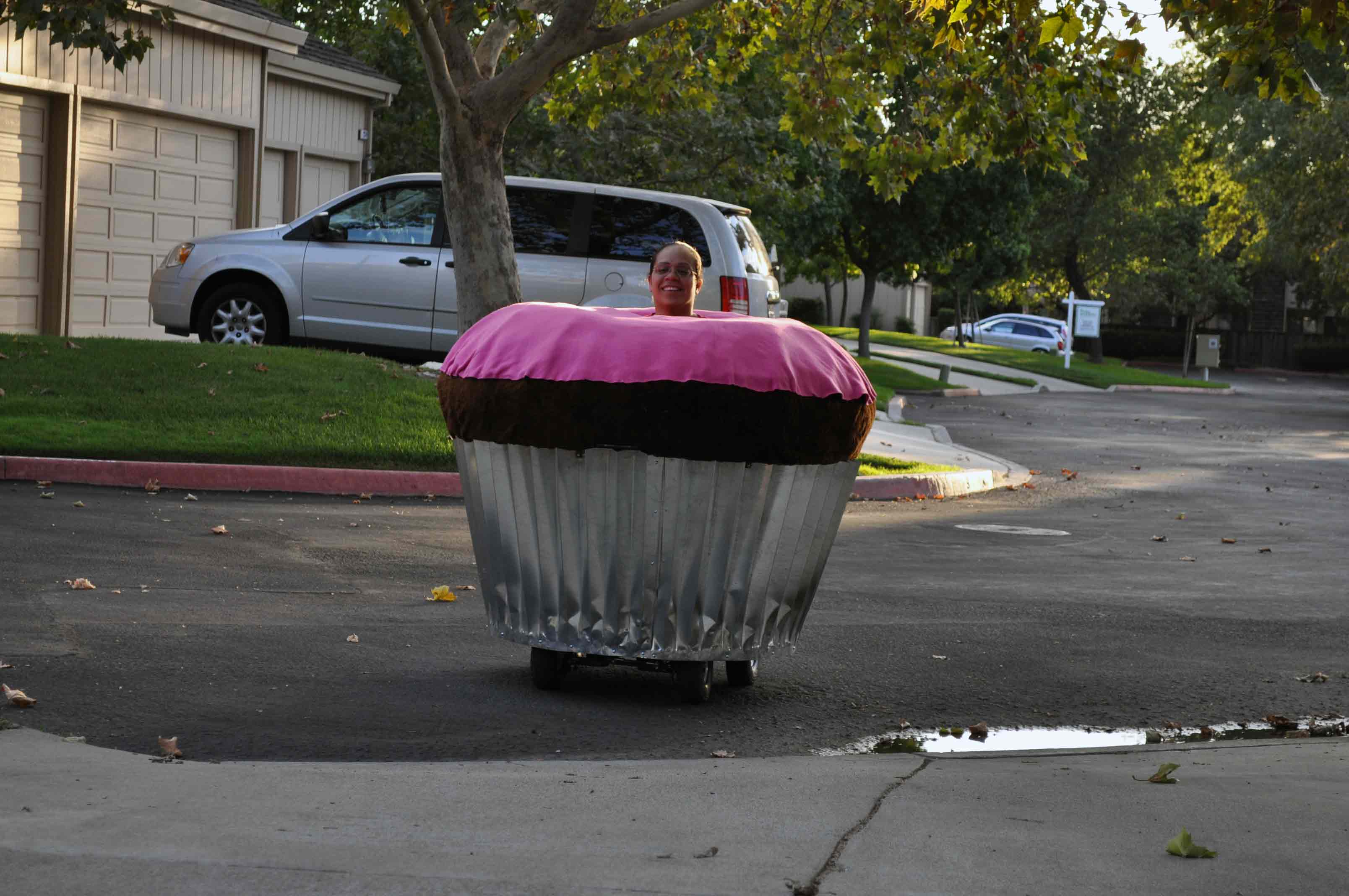
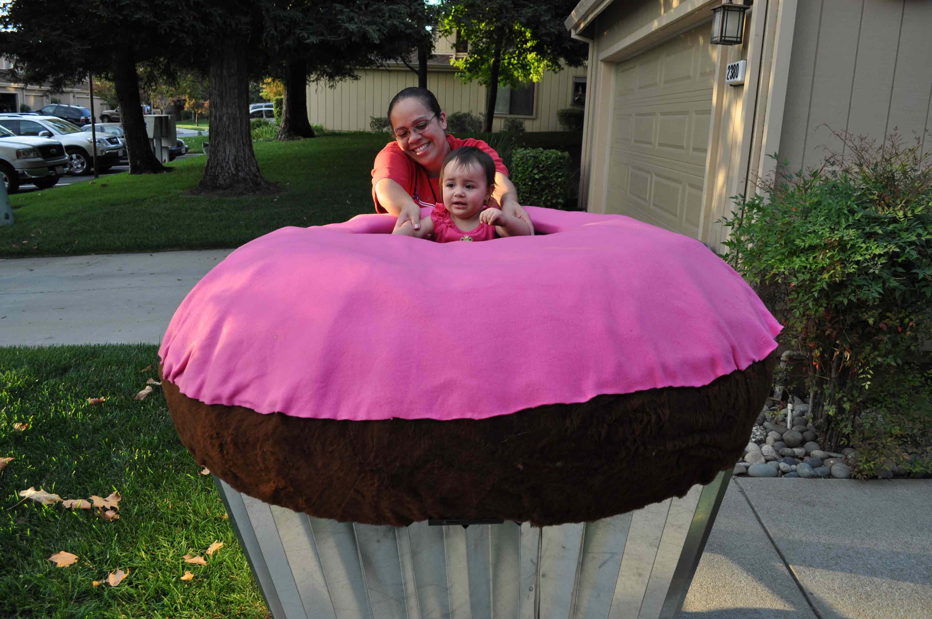
In May of 2008 while exhibiting at the San Mateo Makers Fair I can across a group of drivable muffins. After seeing these I decided I would have to find some time to build one of my own. At the time I was busy with my own exhibit so I did not get a chance to have a close look the muffins that were on display, but I soon found a few pictures on the web and the muffin wiki page at www.acmeart.com/muffins/mediawiki/index.php. The original muffins were dreamed up by Lisa Pongrace and as of this project there are about 16 cars.
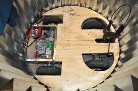
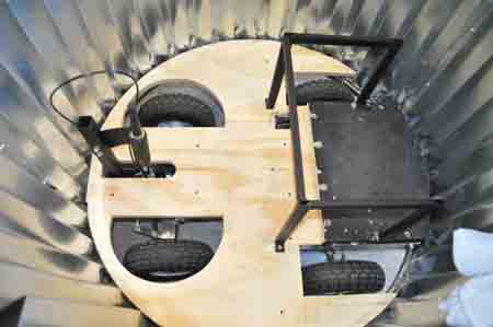
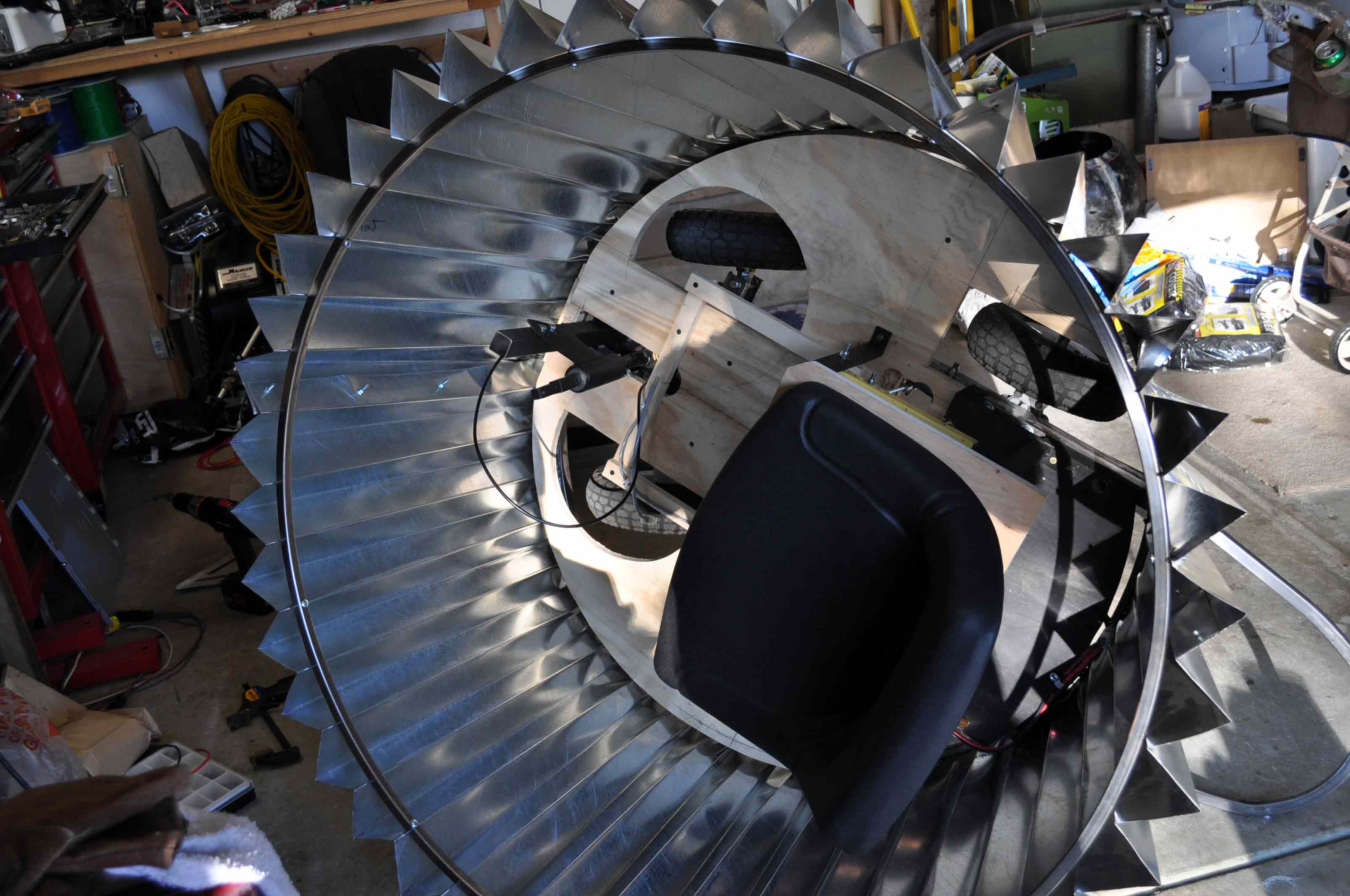
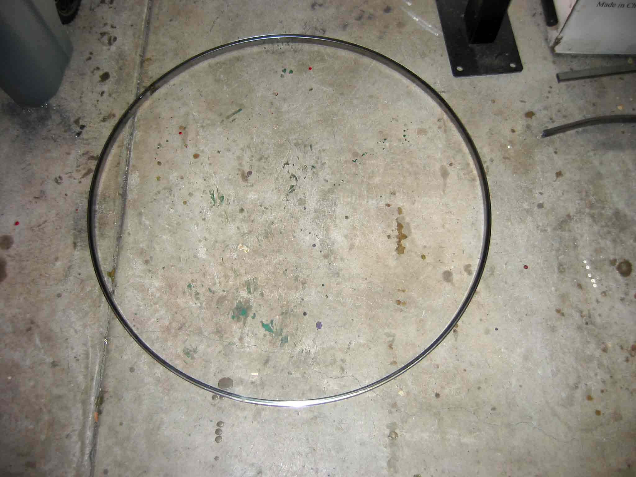
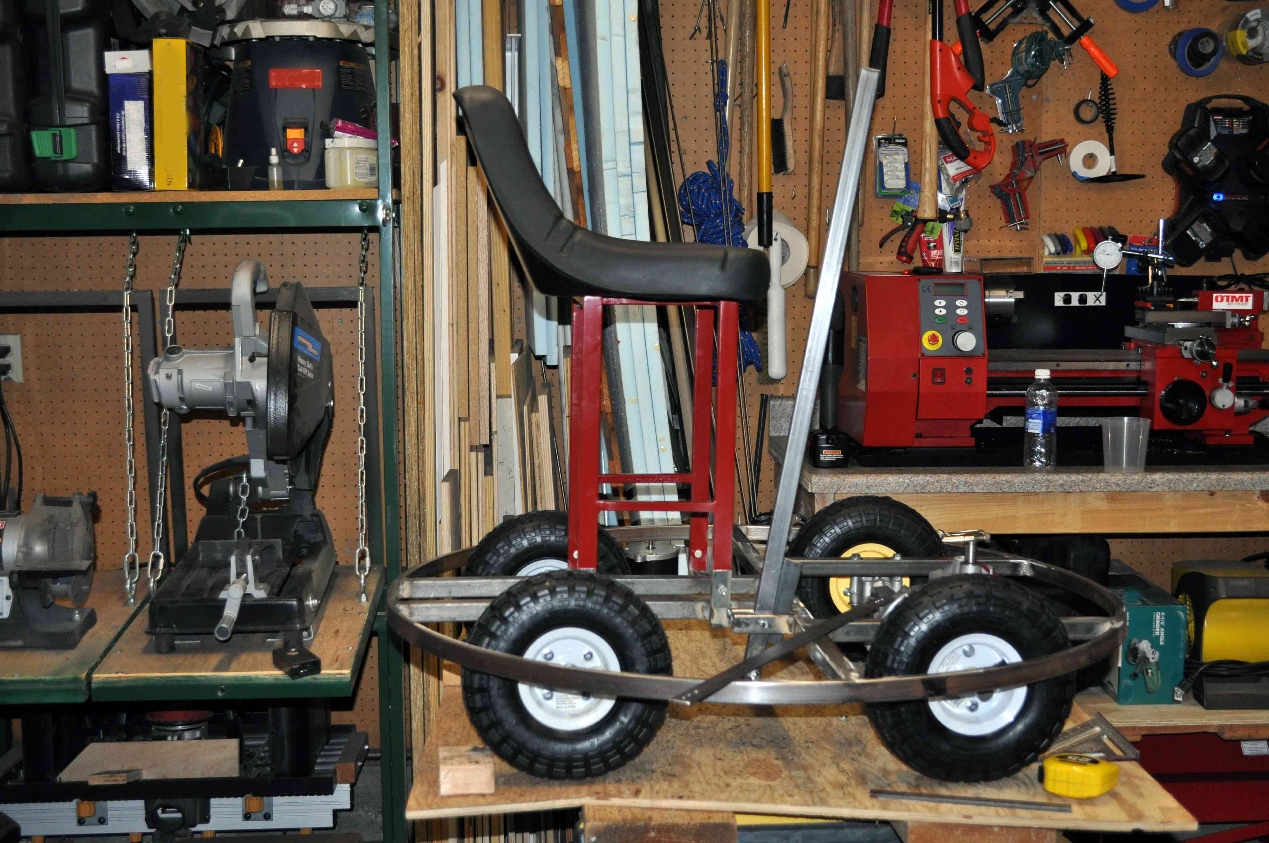
After scrounging a few pictures while waiting some time to get approved for the muffin mailing list, I decided that a muffin was somewhere between 36 and 48 inches after seeing a picture of one sitting on a pallet. I played with some scratch paper and measured the back of the car and decided I needed to have a diameter of 41 inches or less to fit in the car disassembled. Next car I get will once again be able to tow a trailer. Anyway I decided to leave a little room for the fit in the car and went with 39 inches for the outside diameter of the chase.
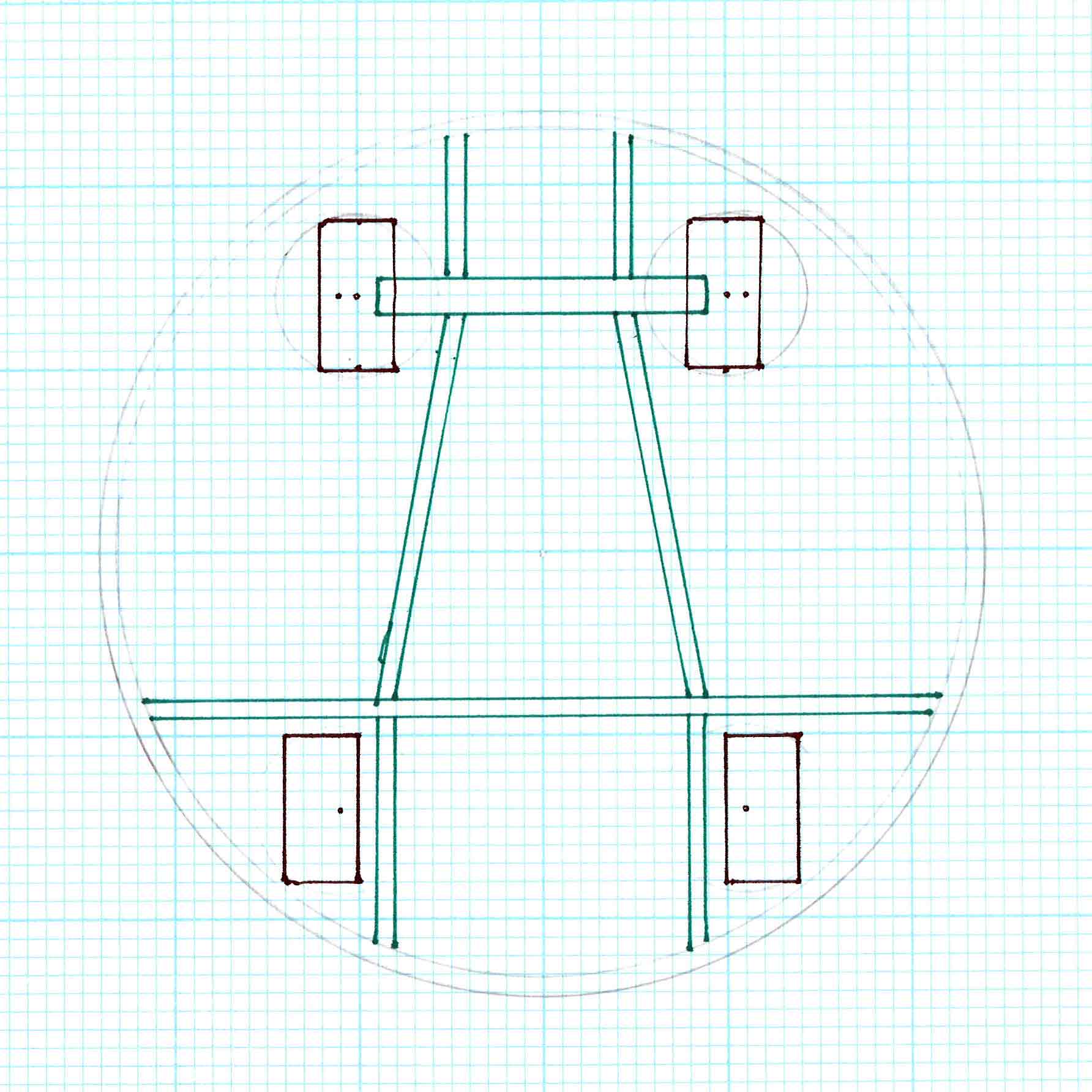
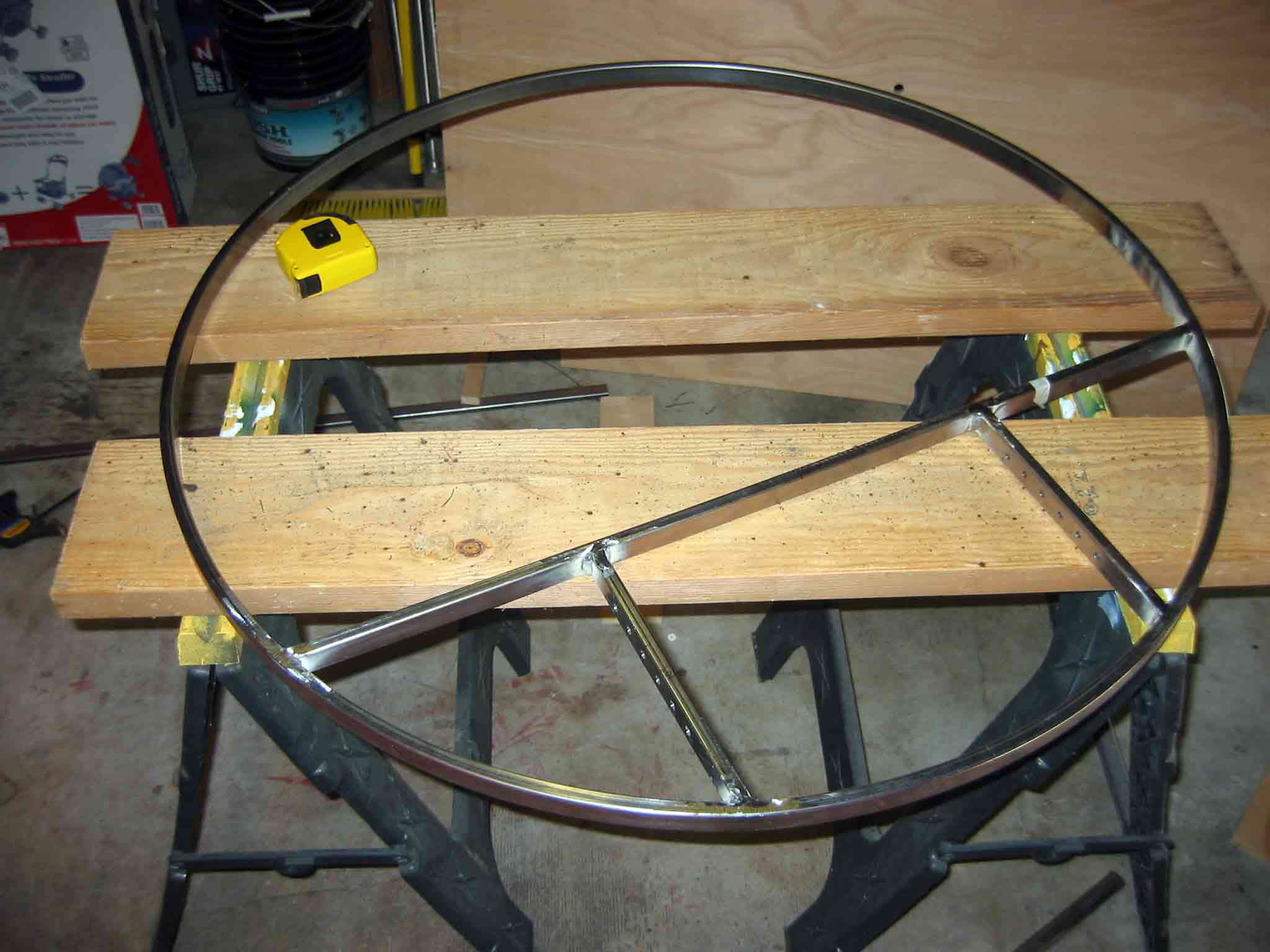
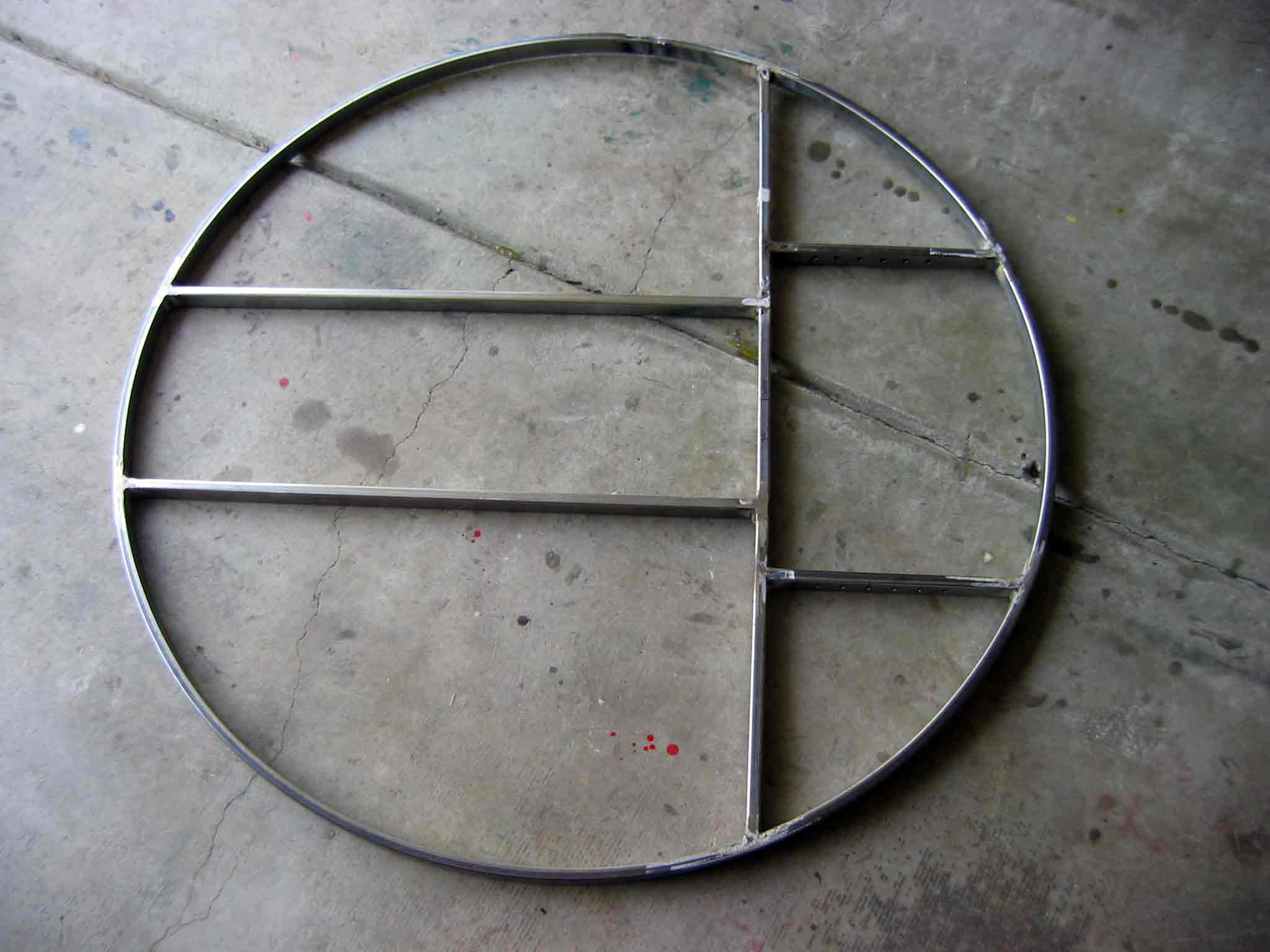
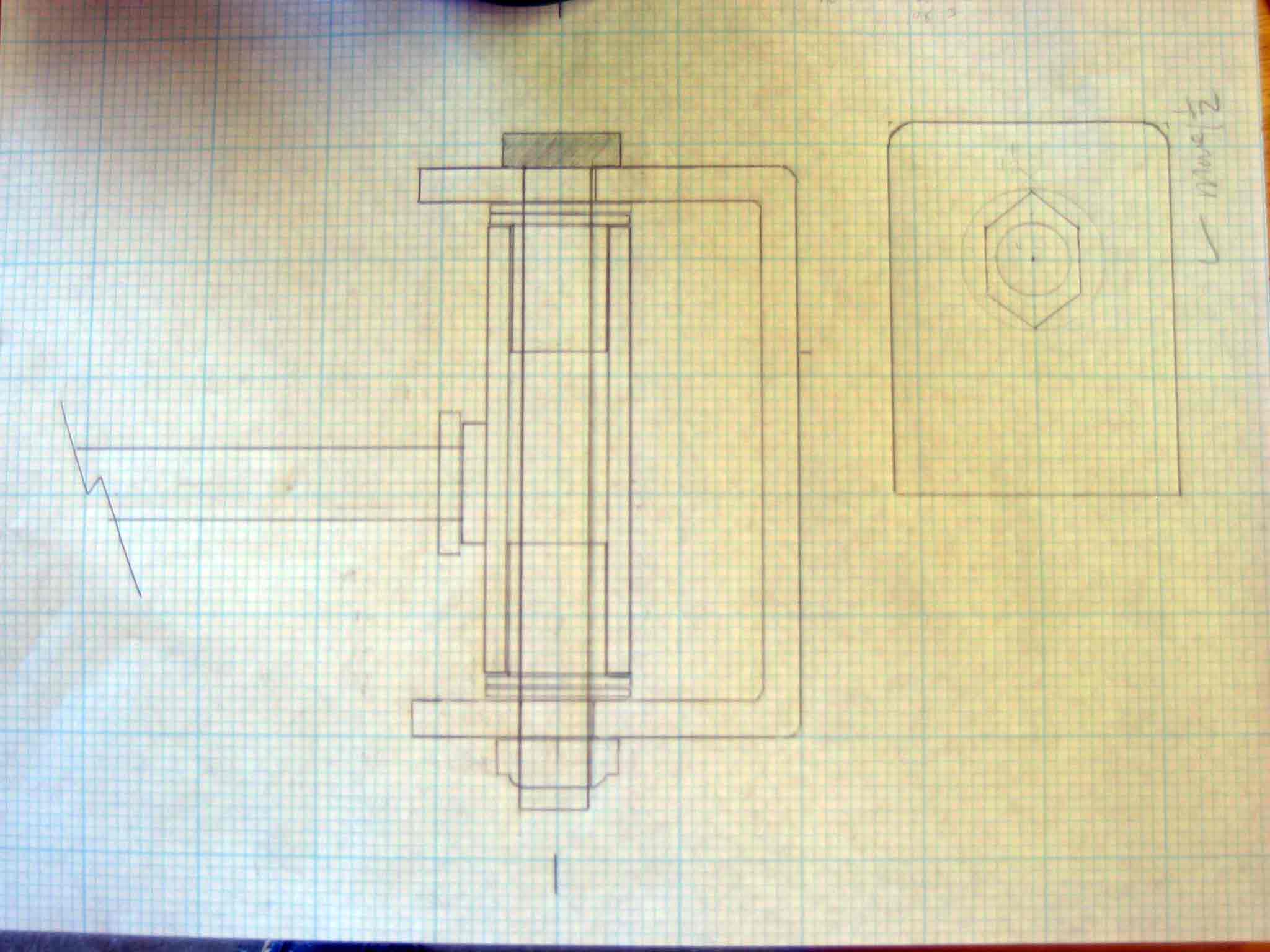
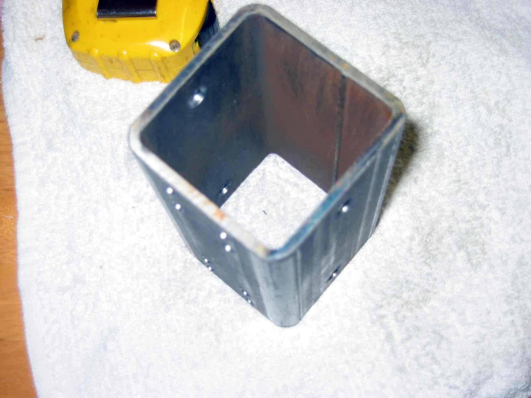
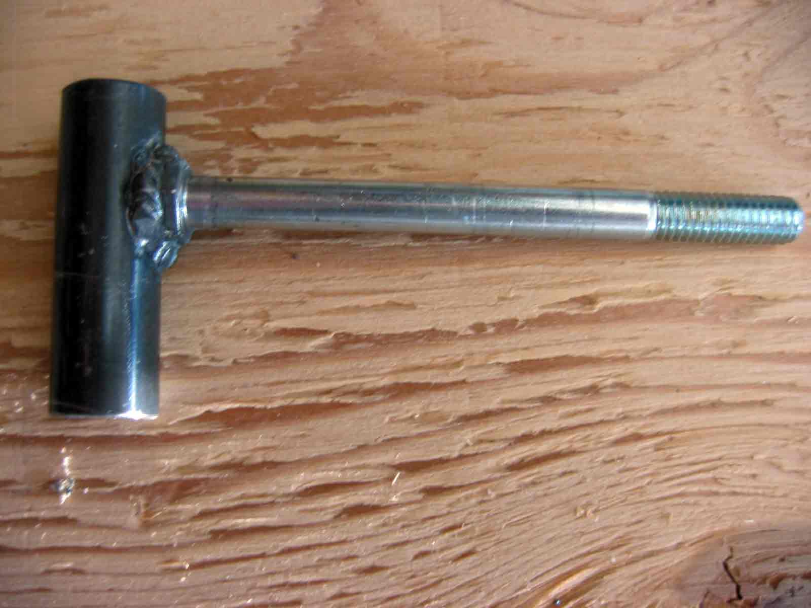
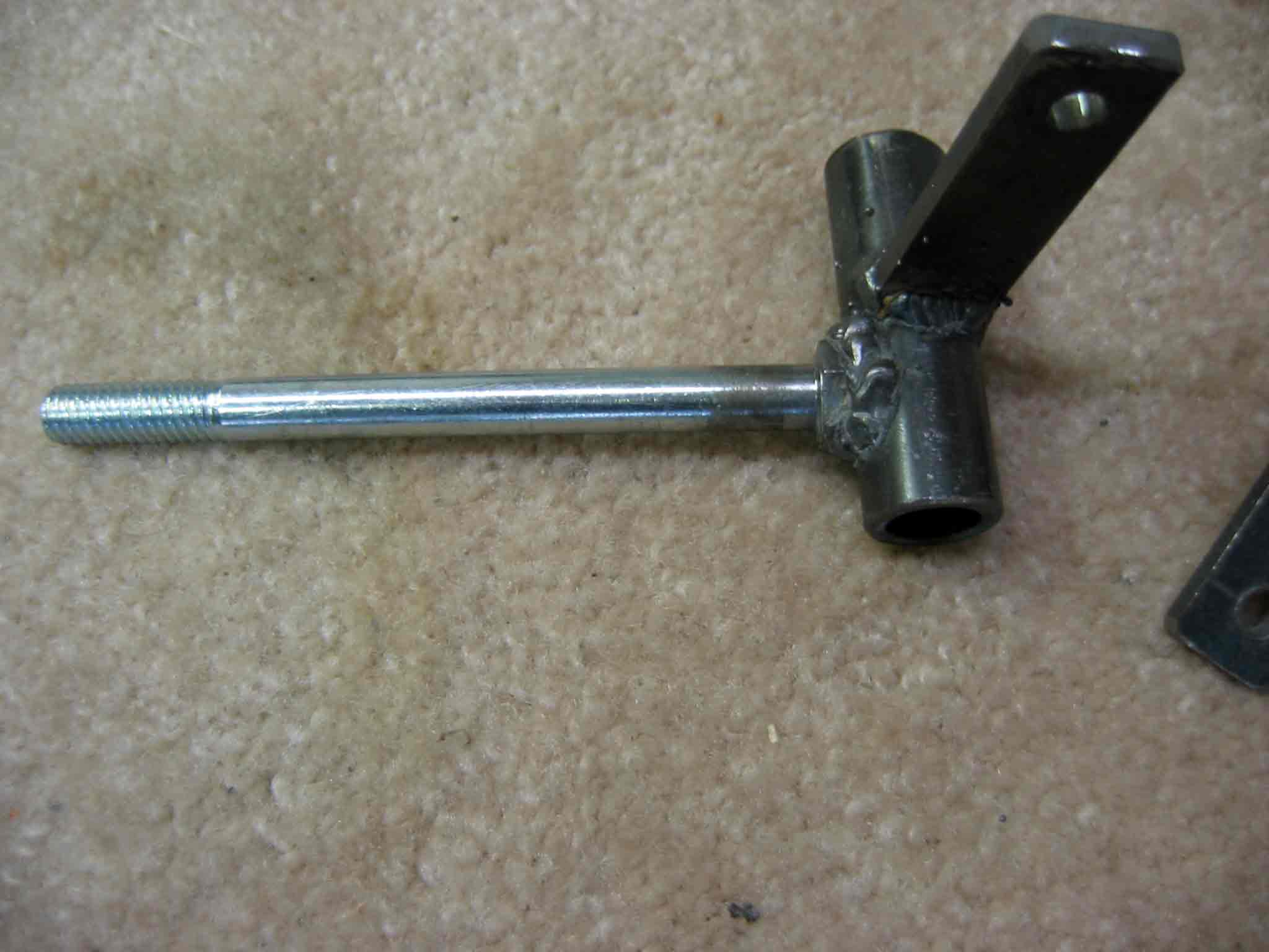
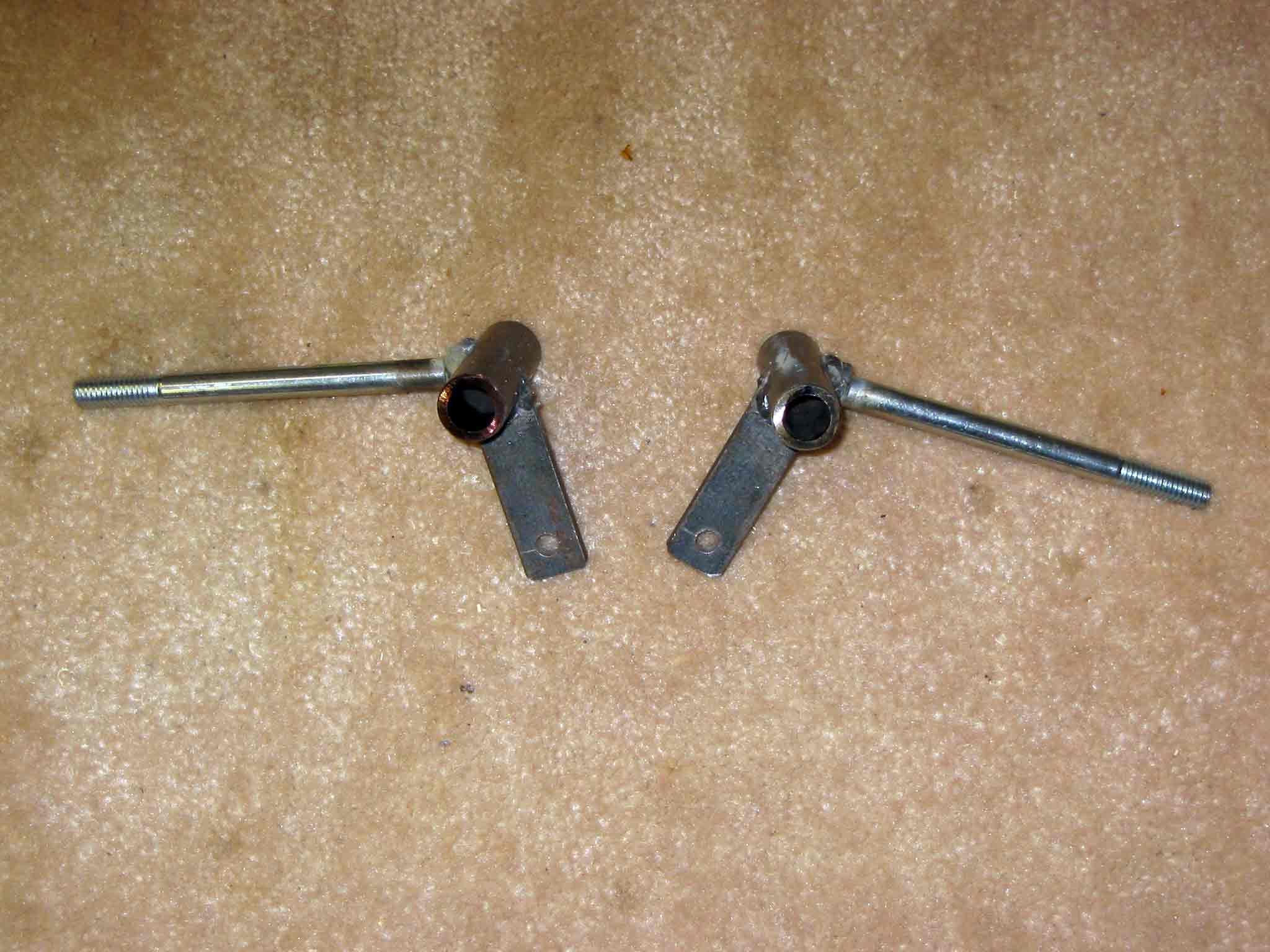
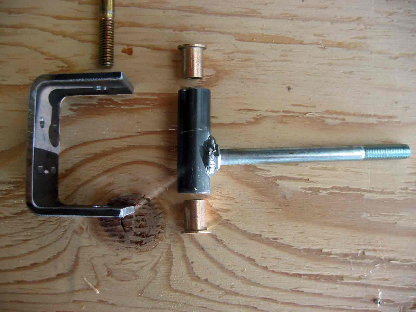
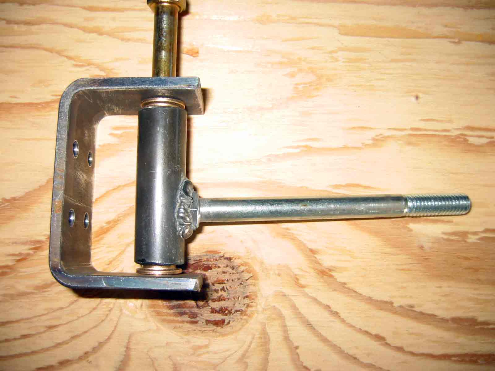
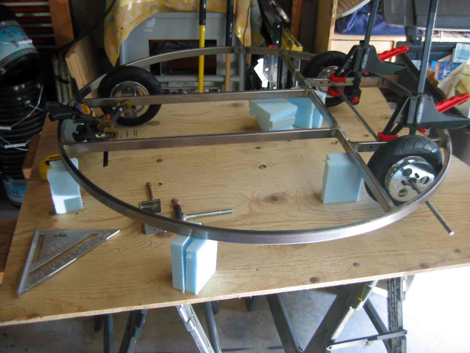
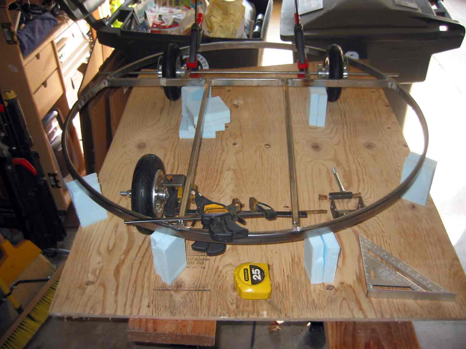
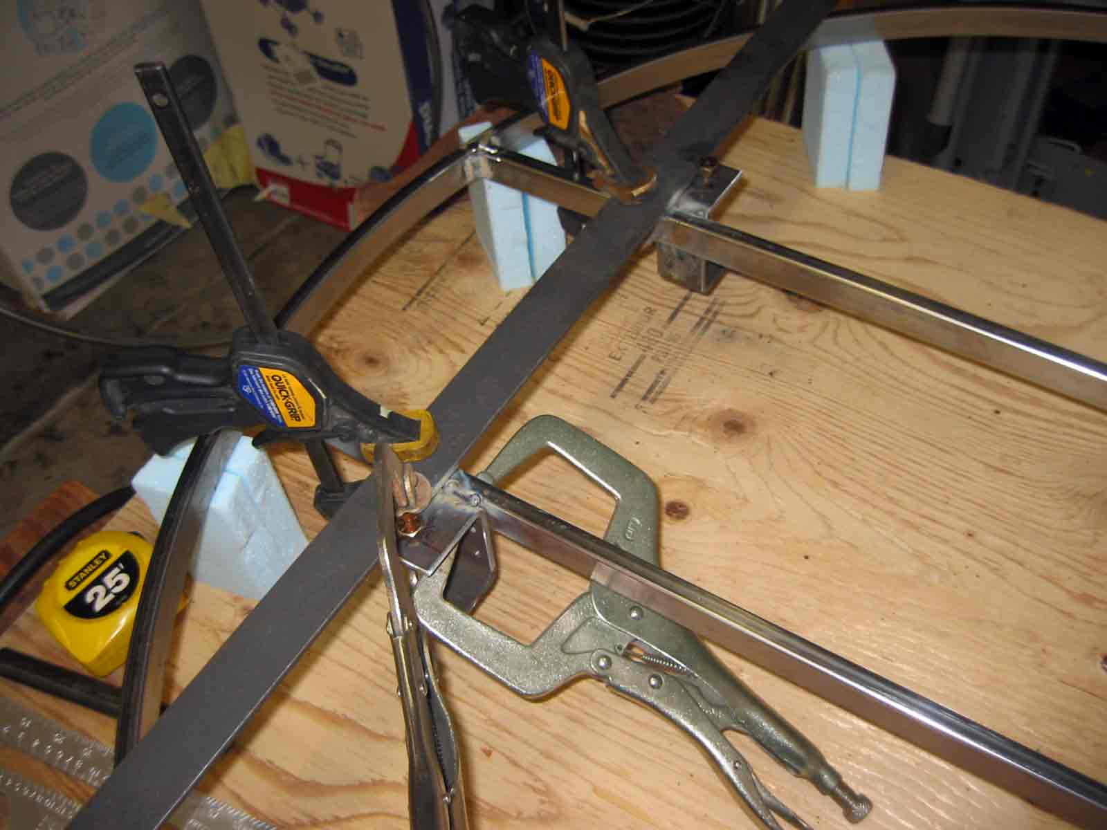
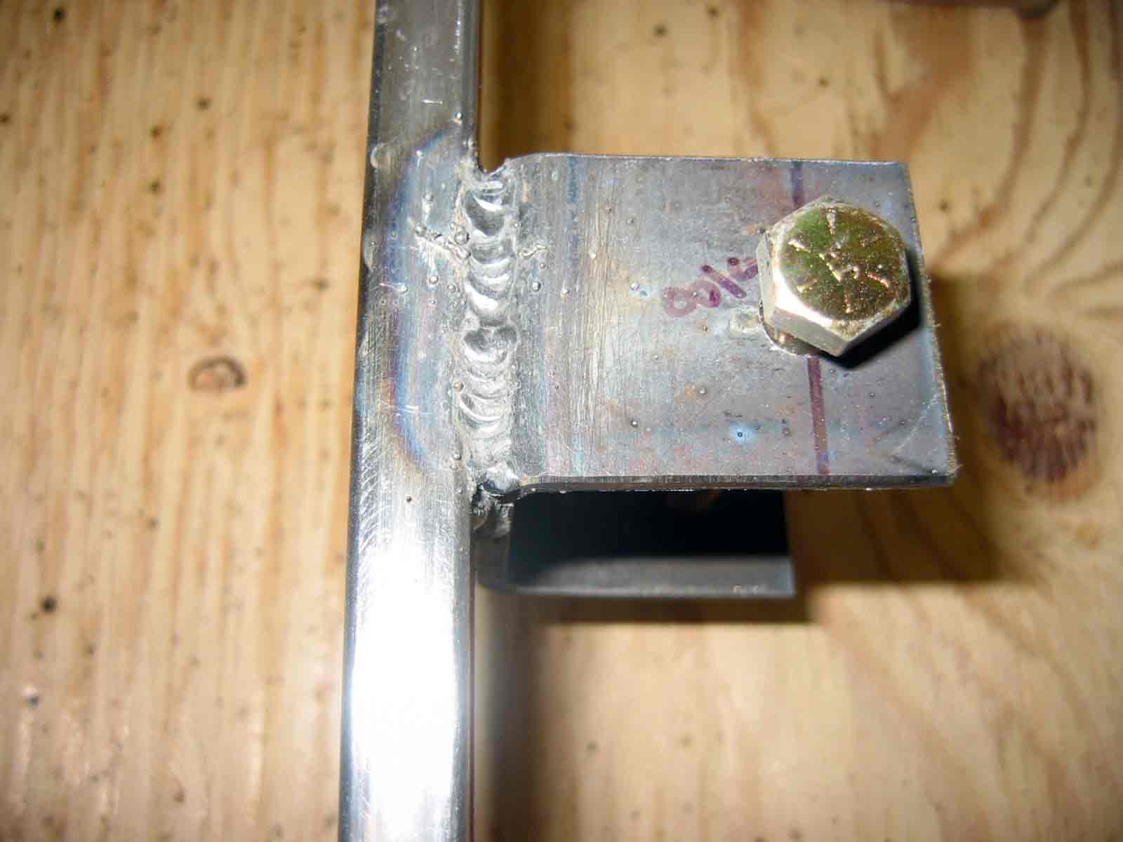
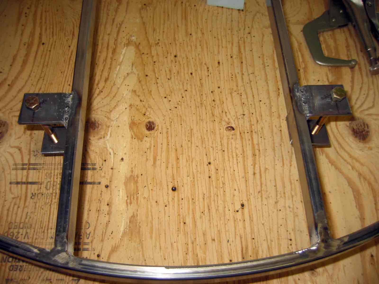
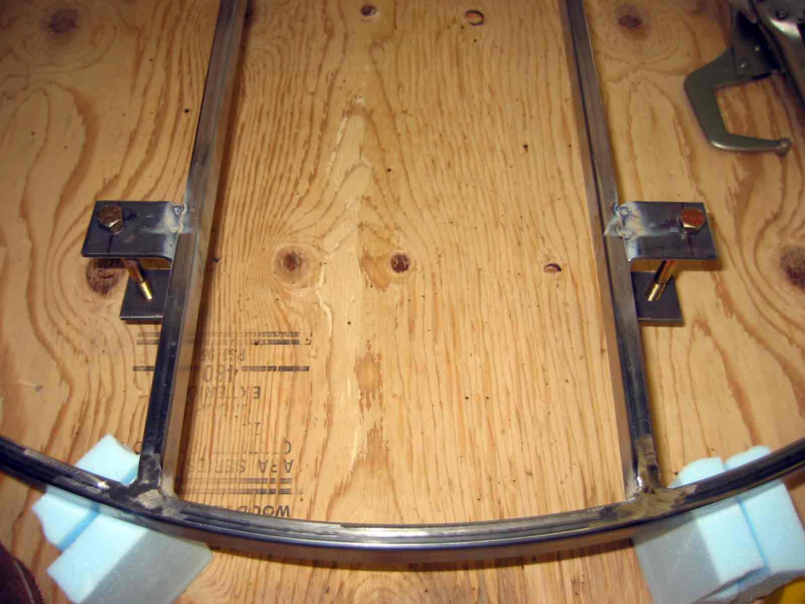
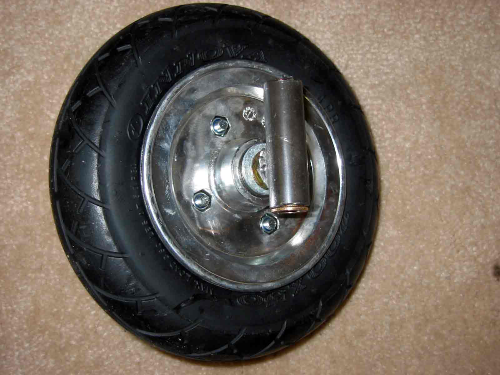
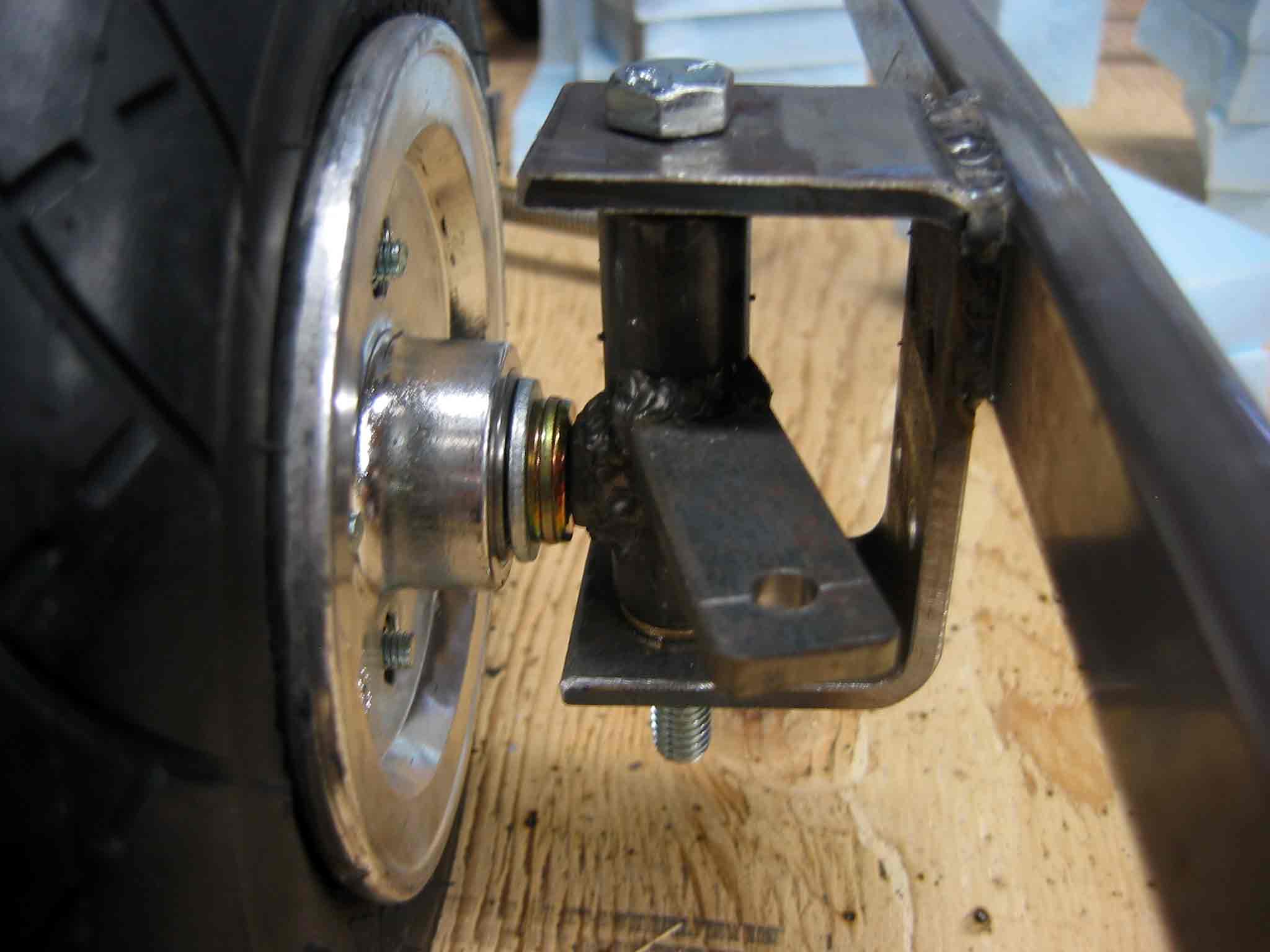
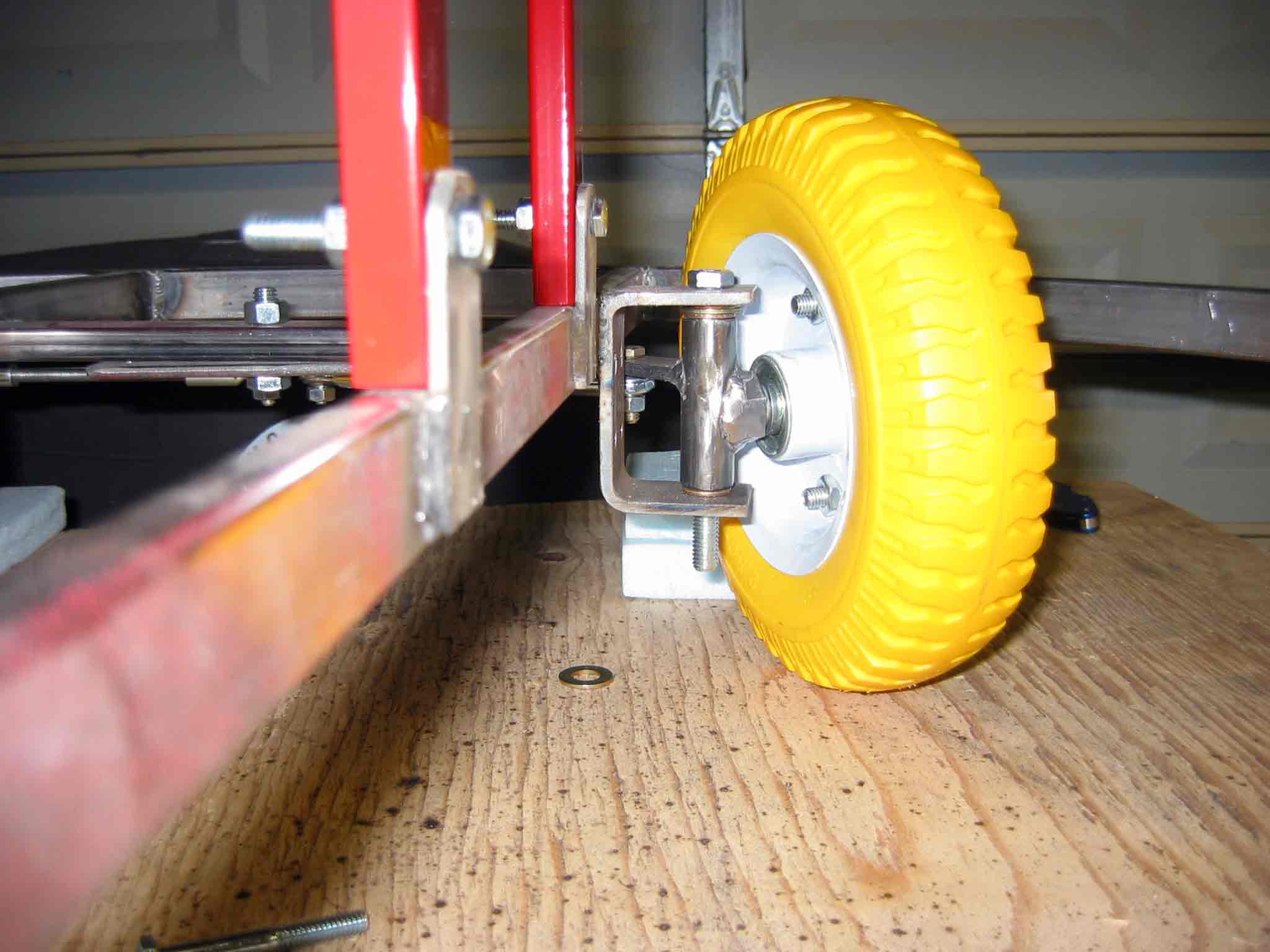
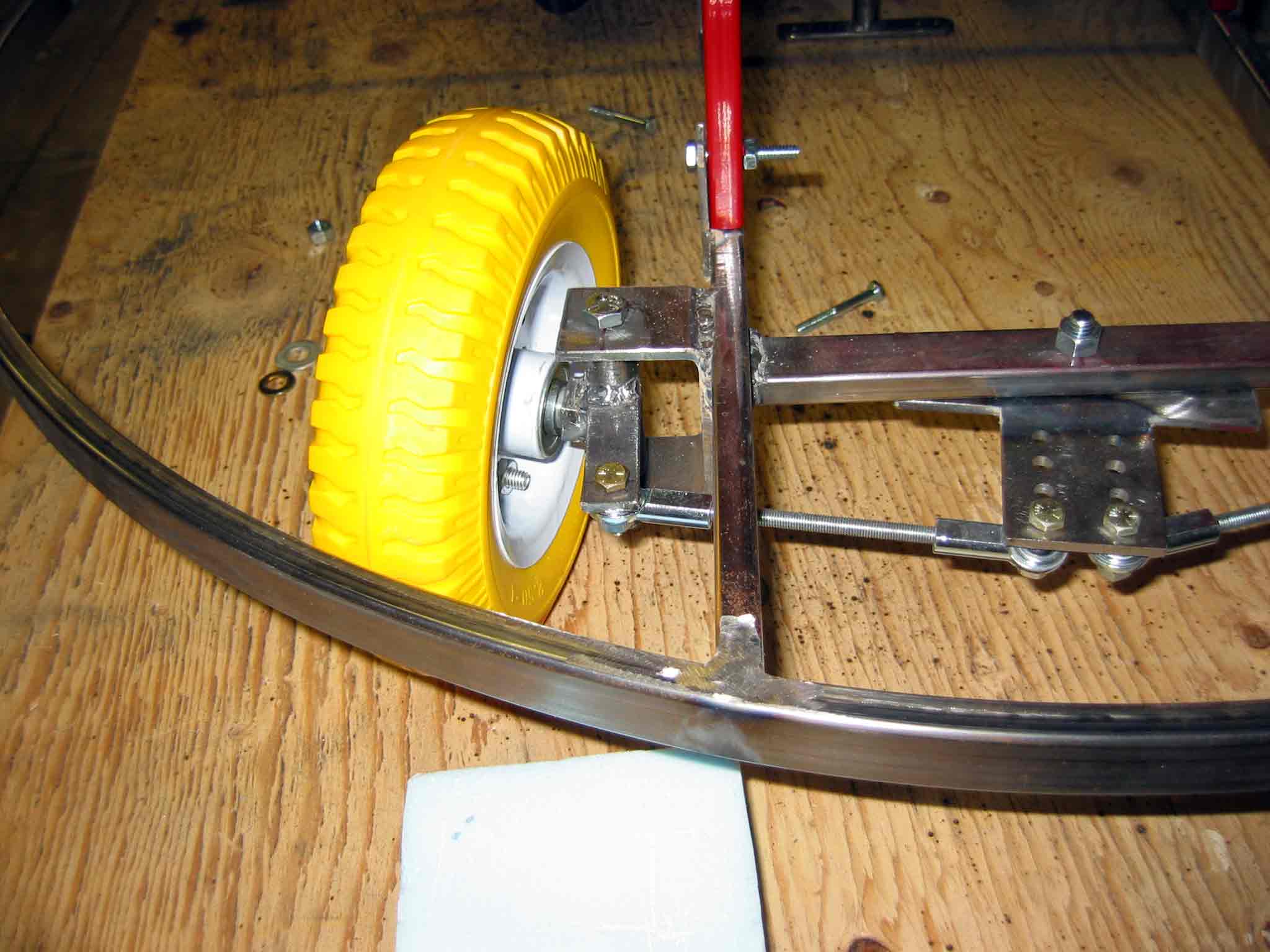
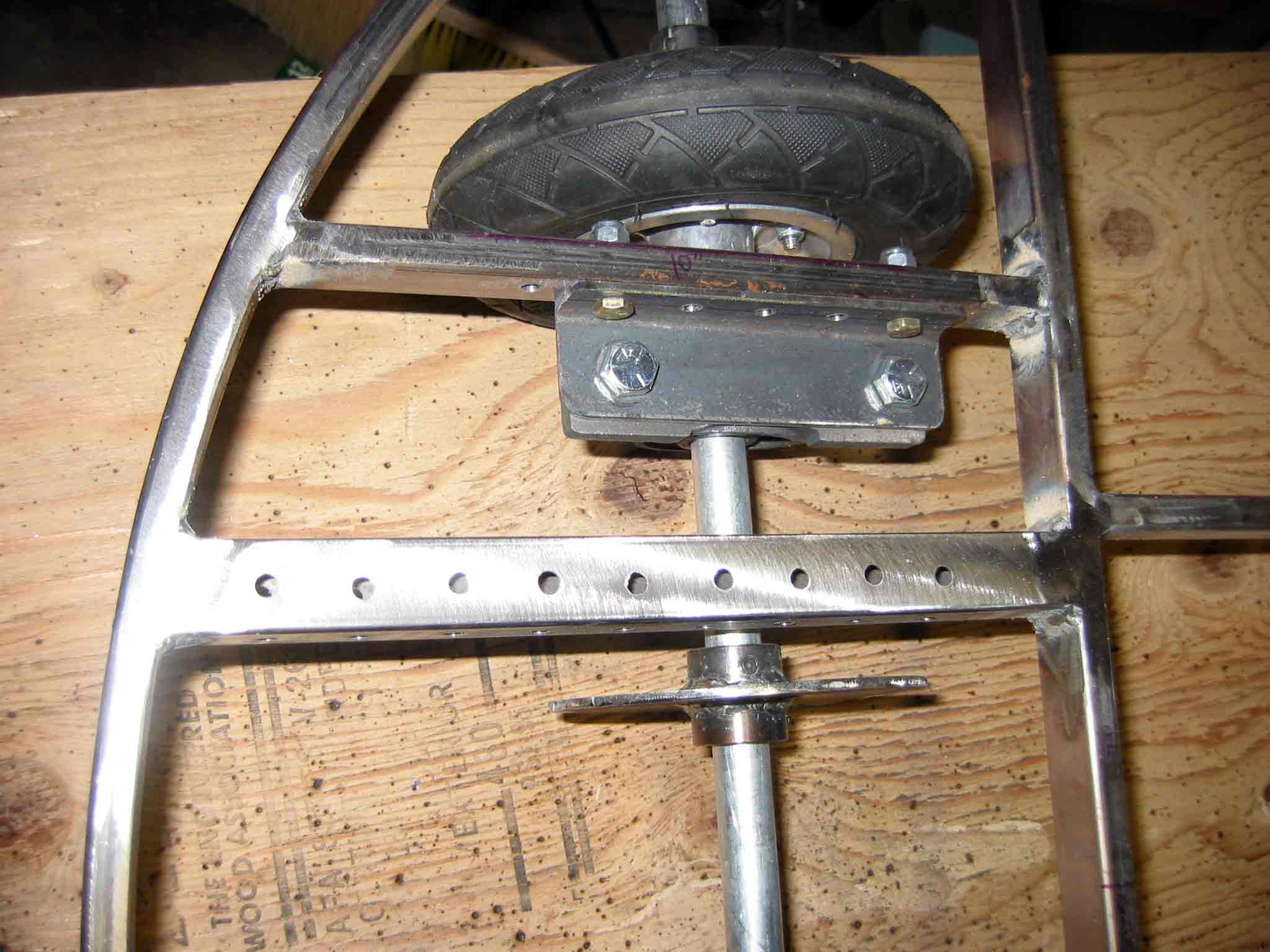
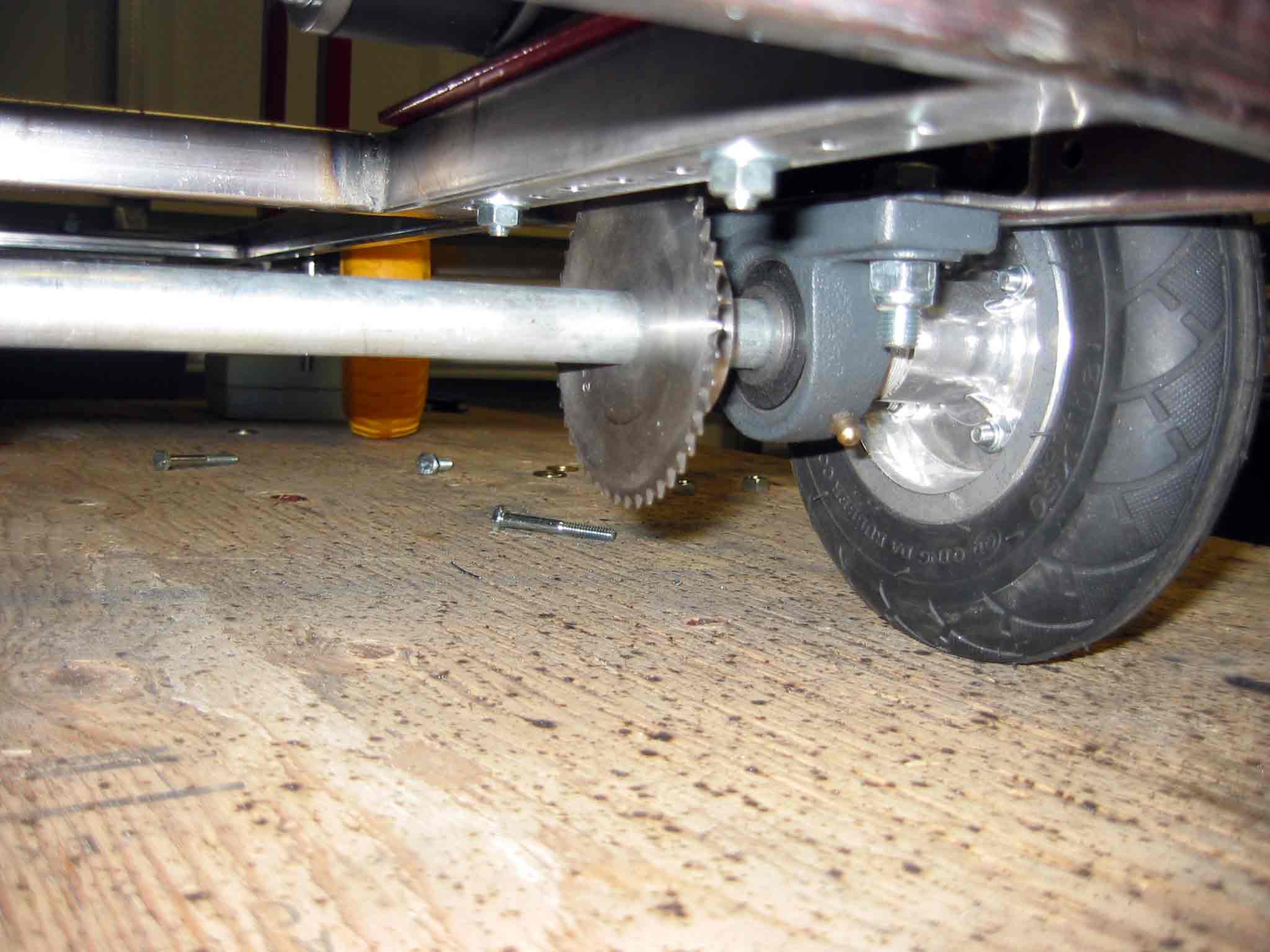
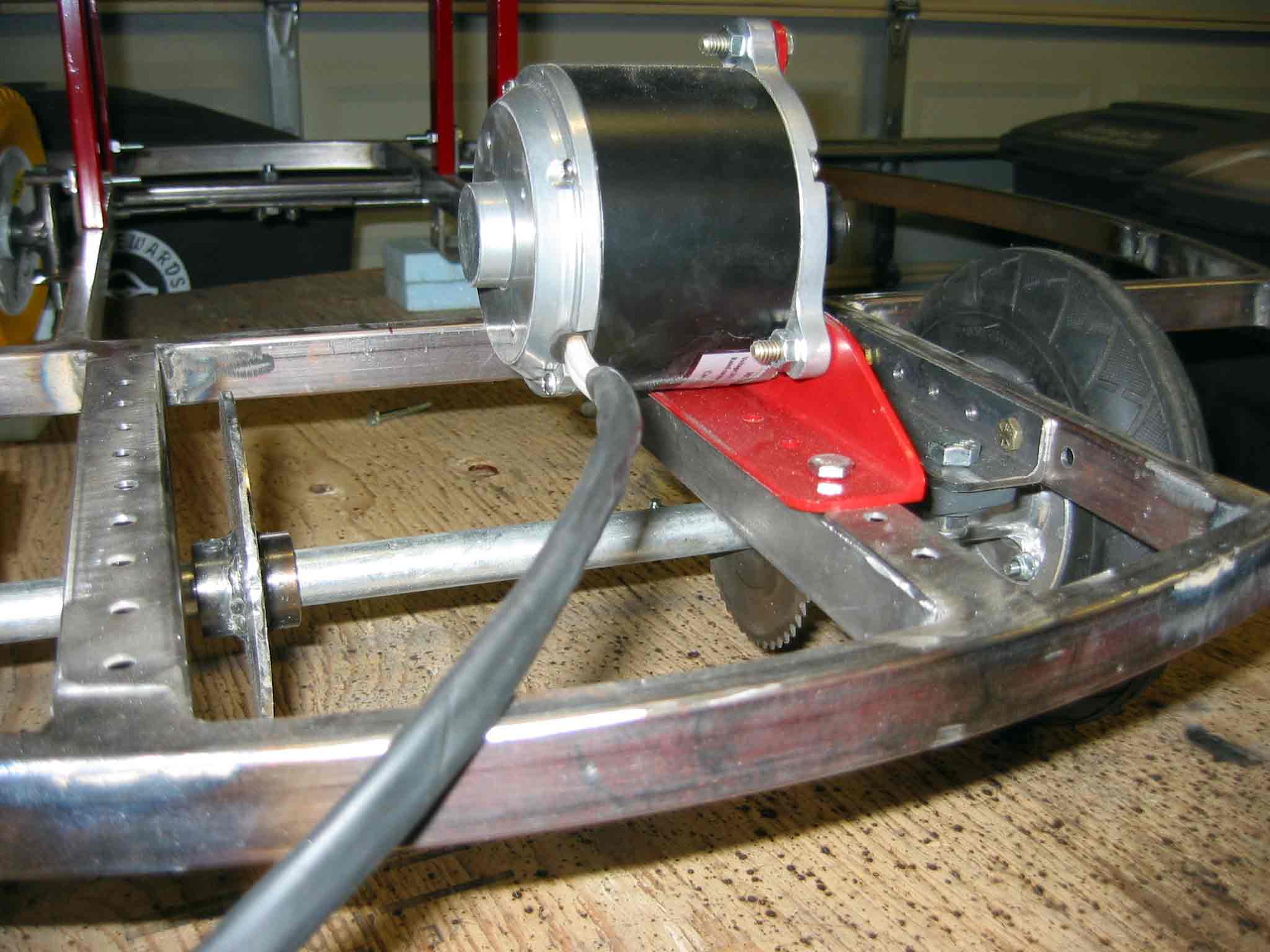
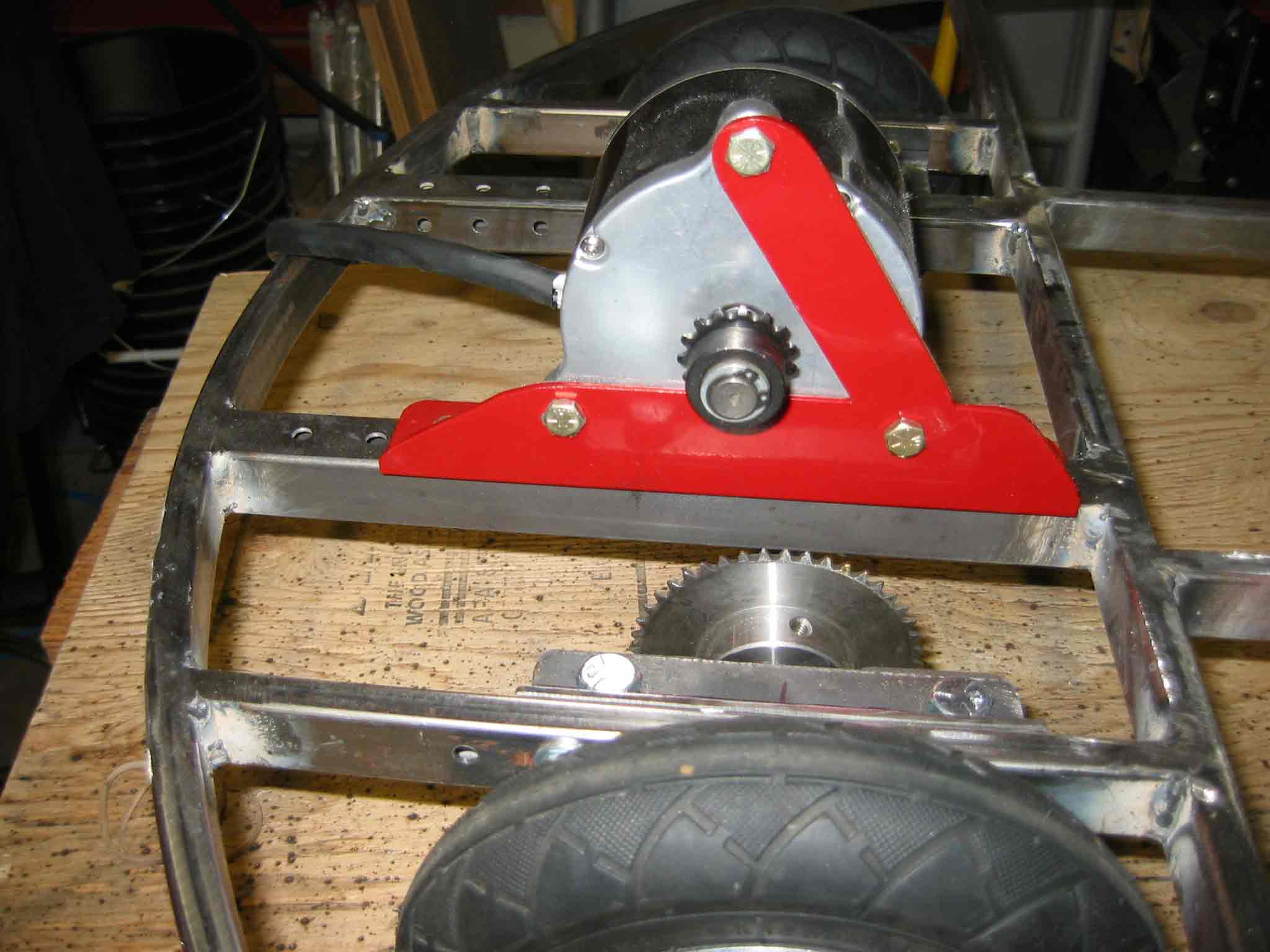
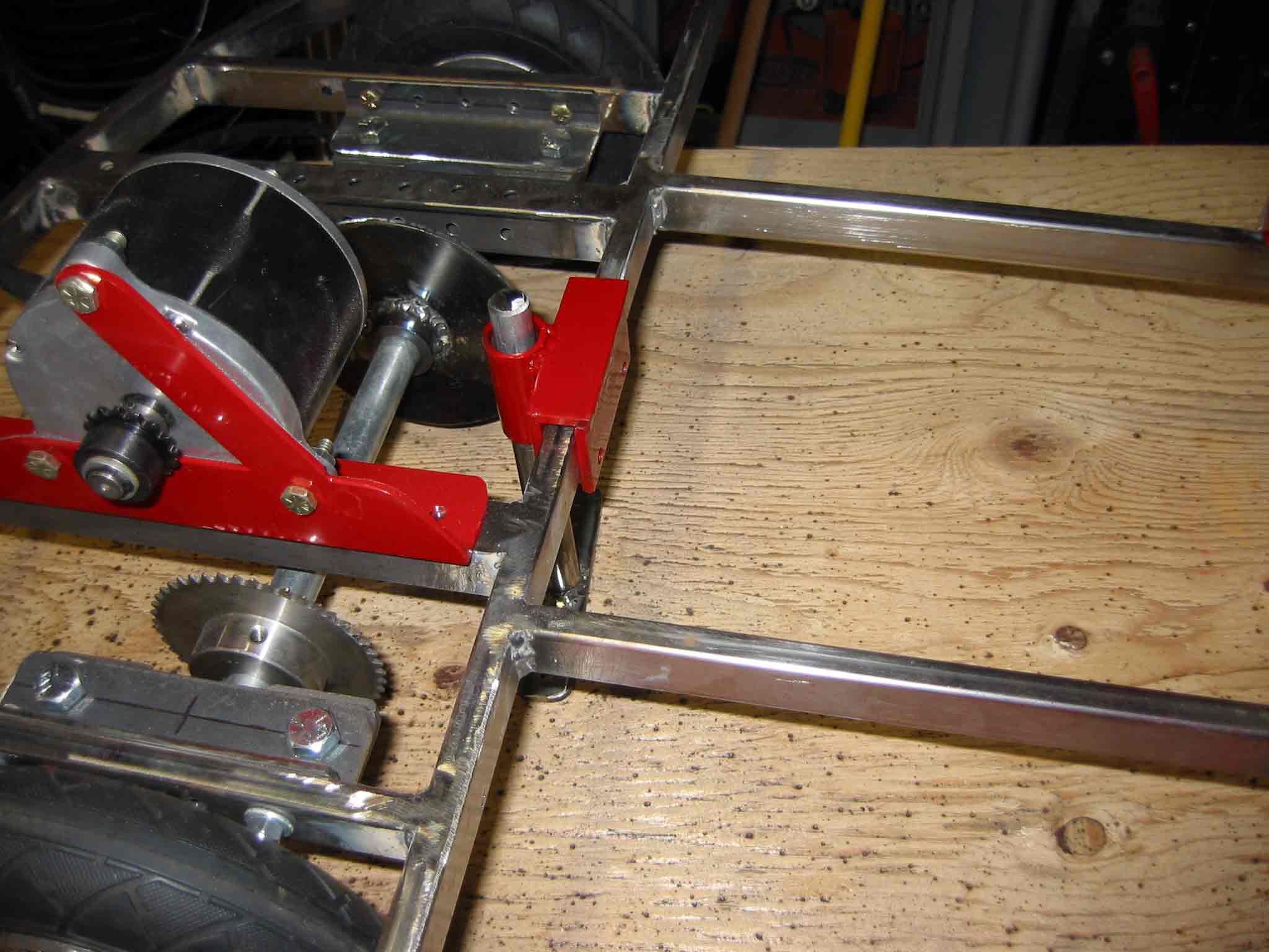
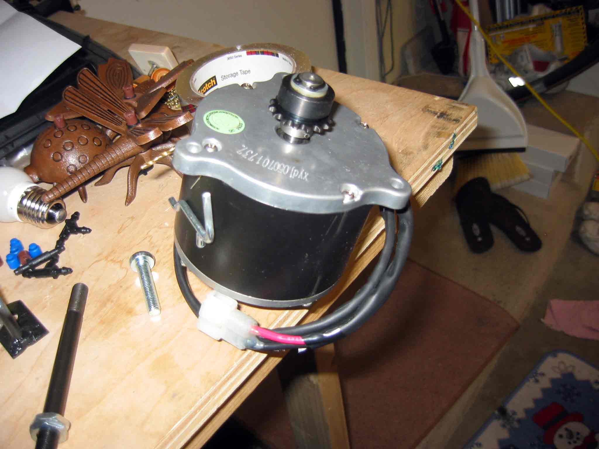
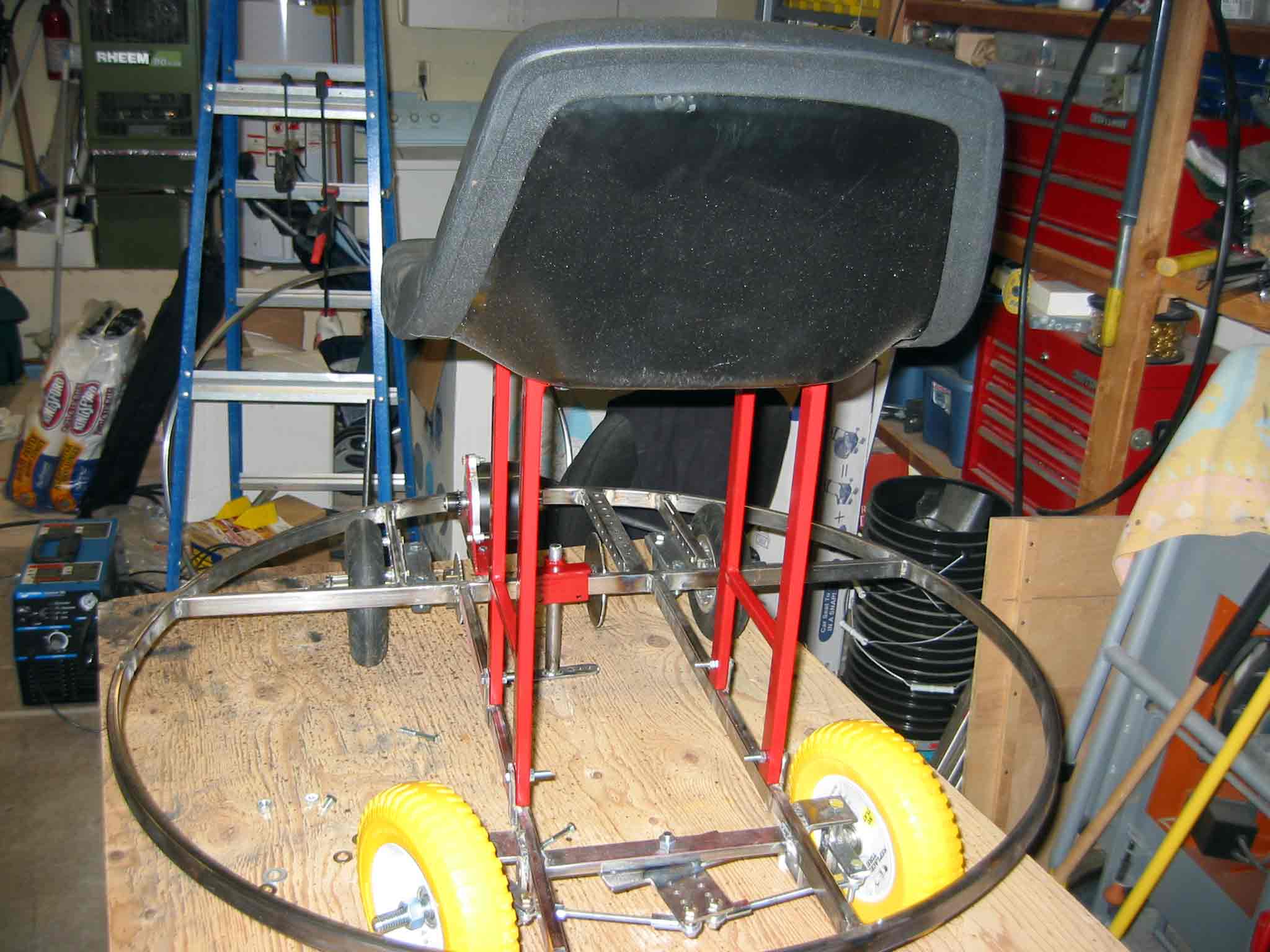
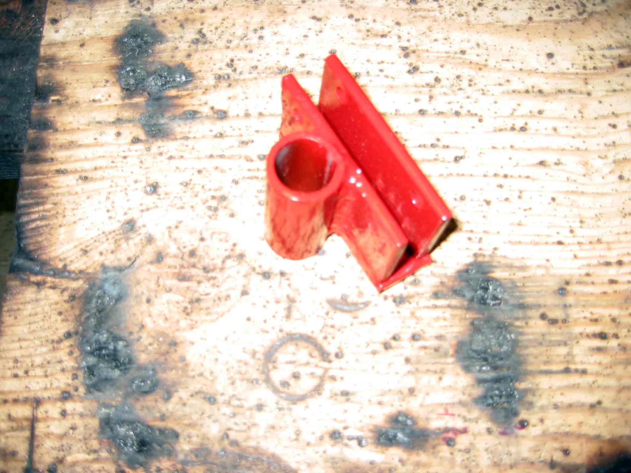
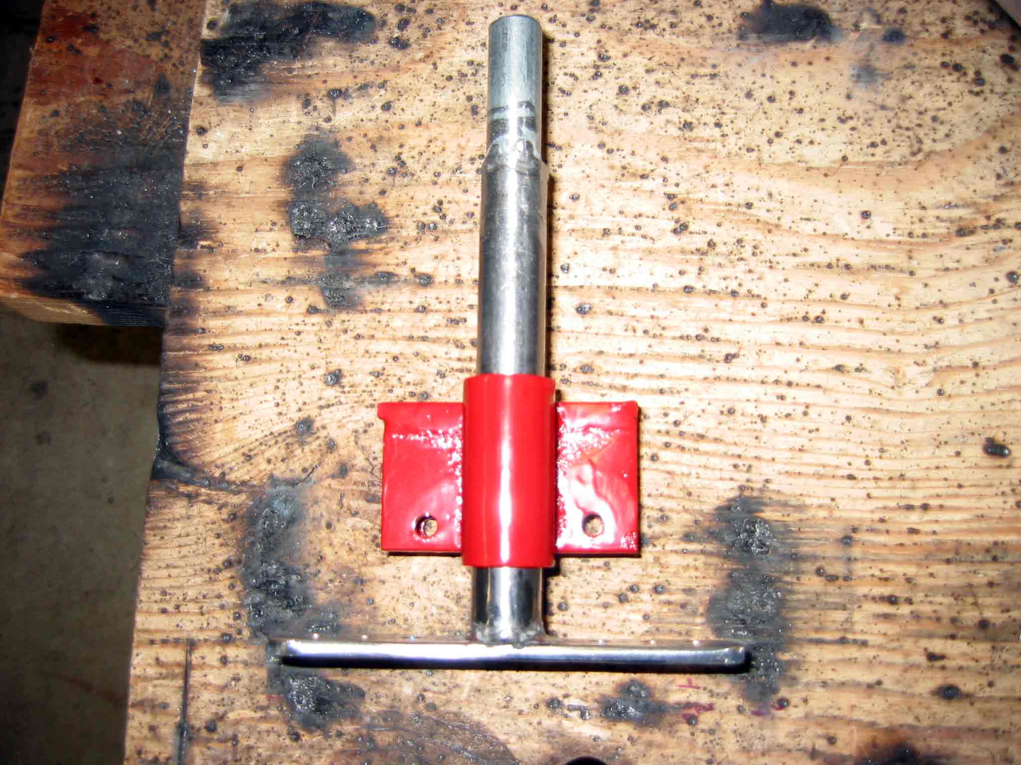
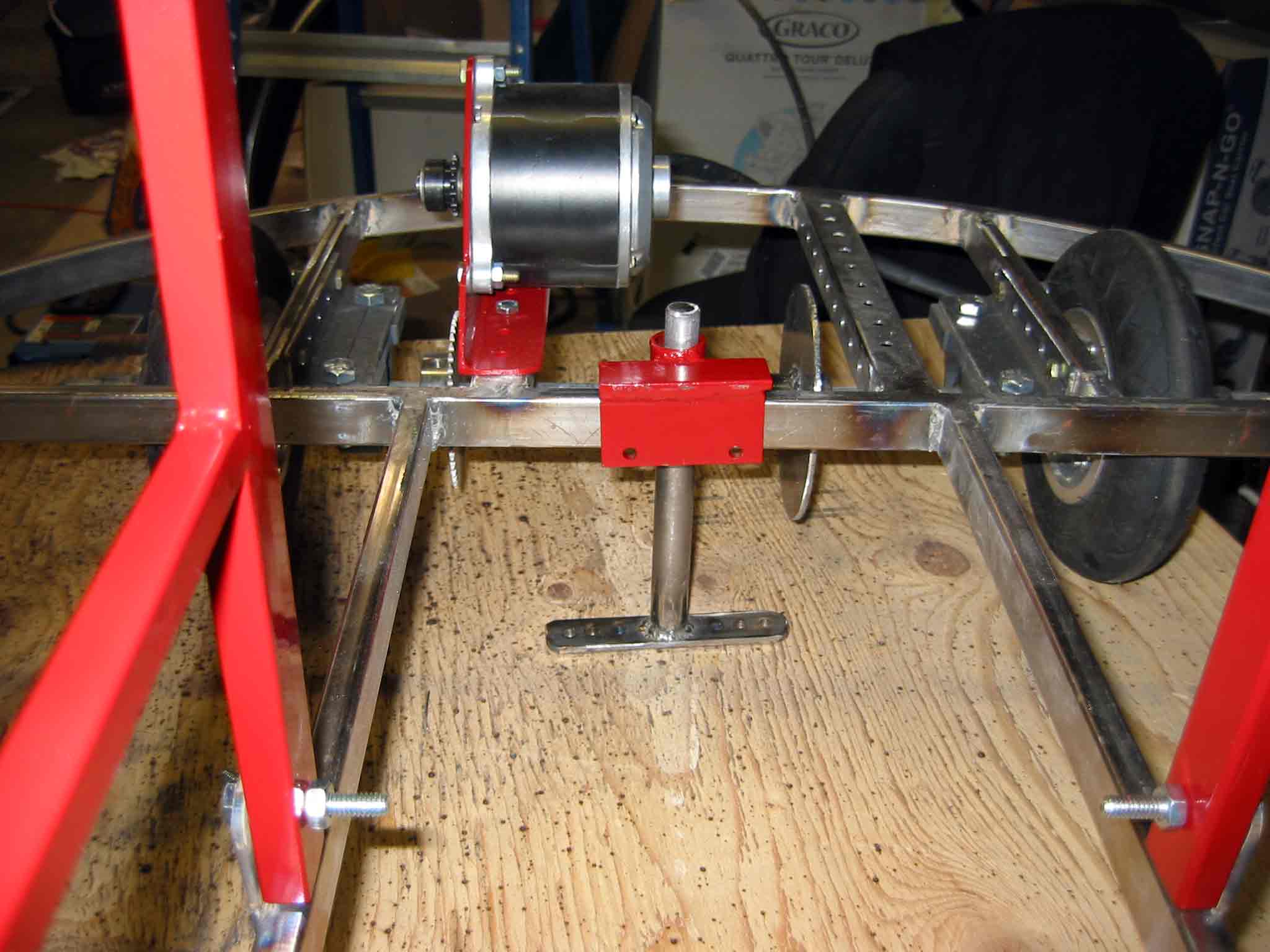
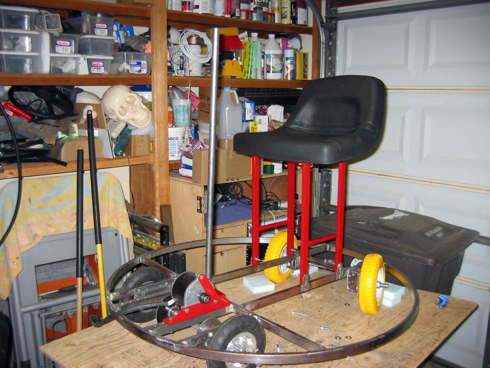
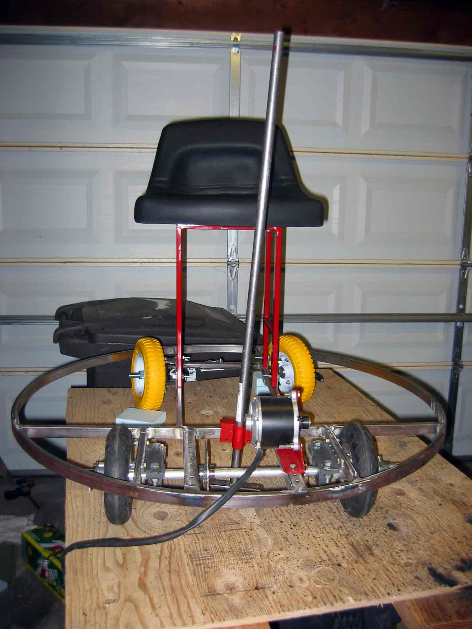
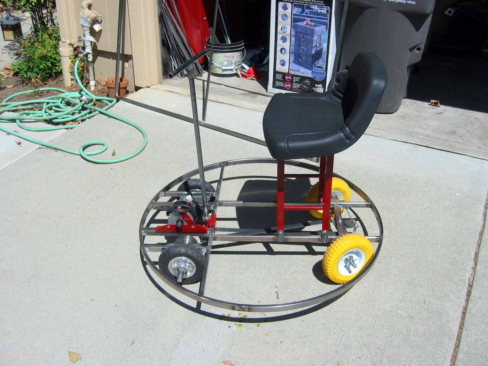
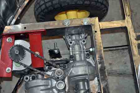
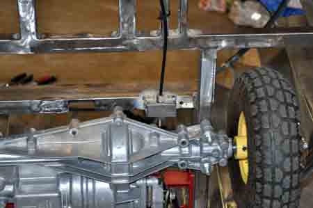
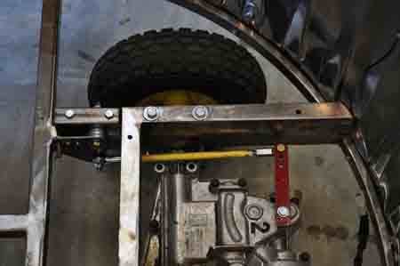
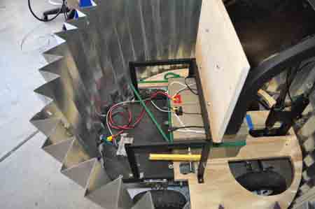
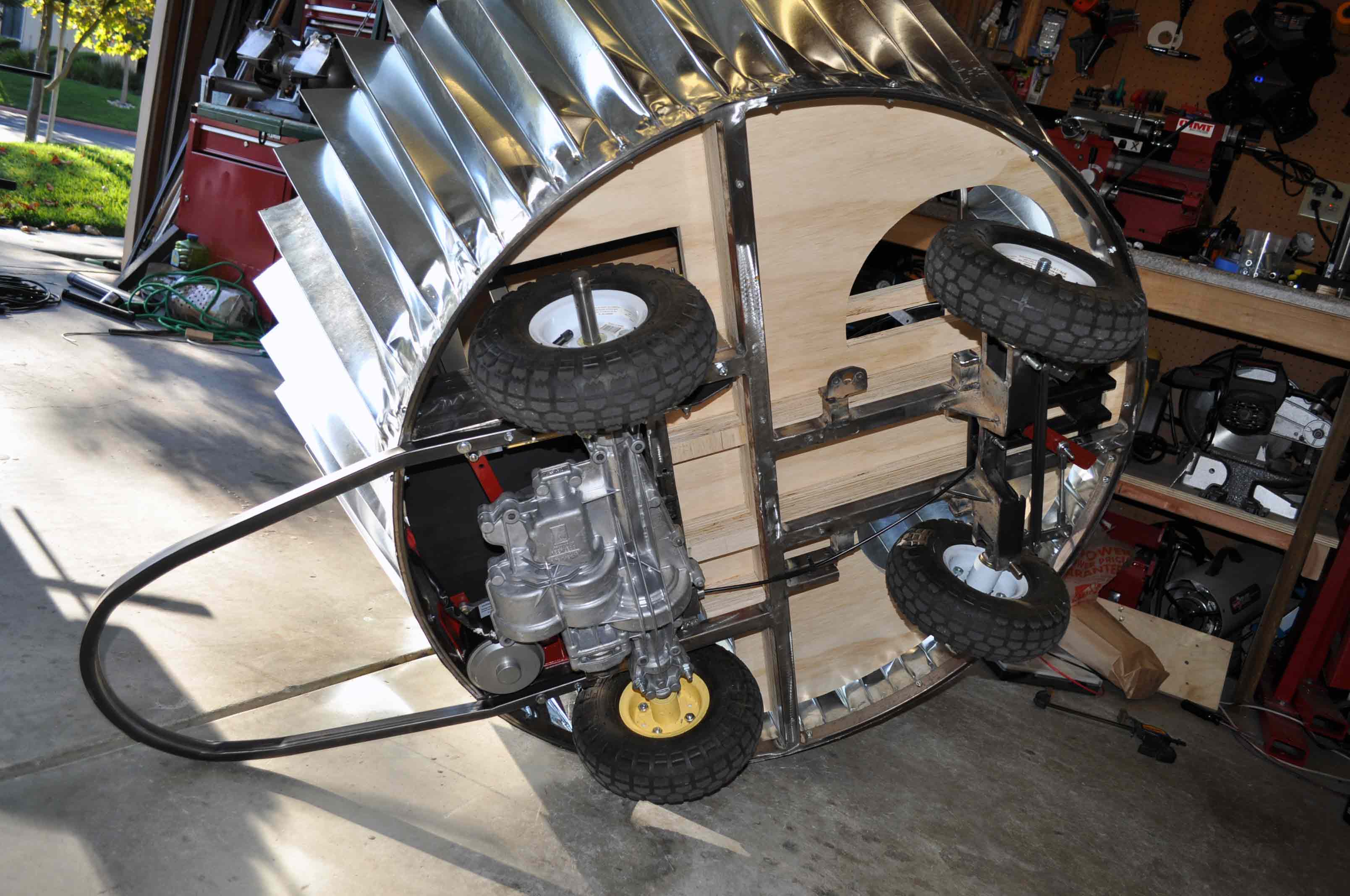
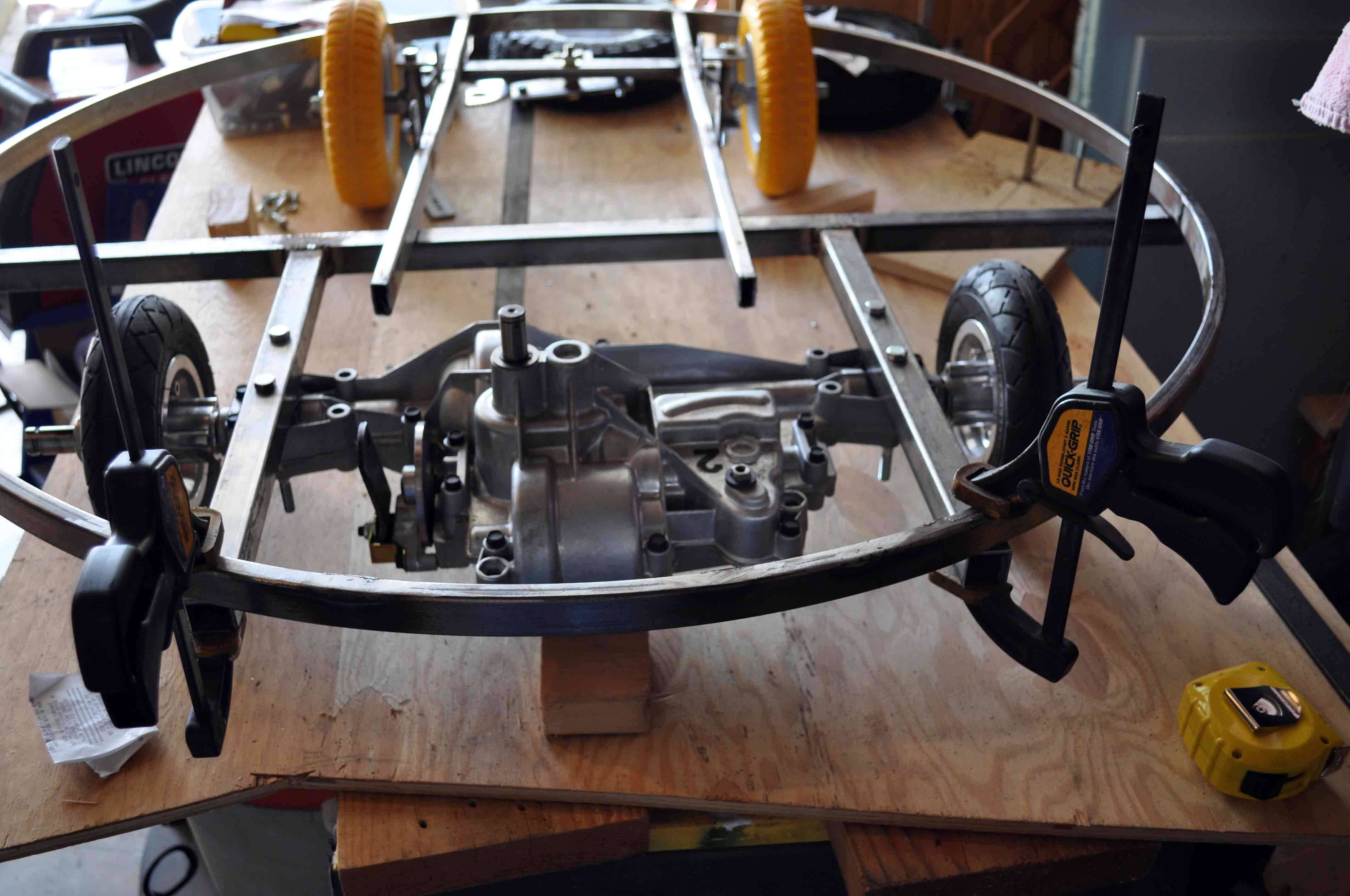
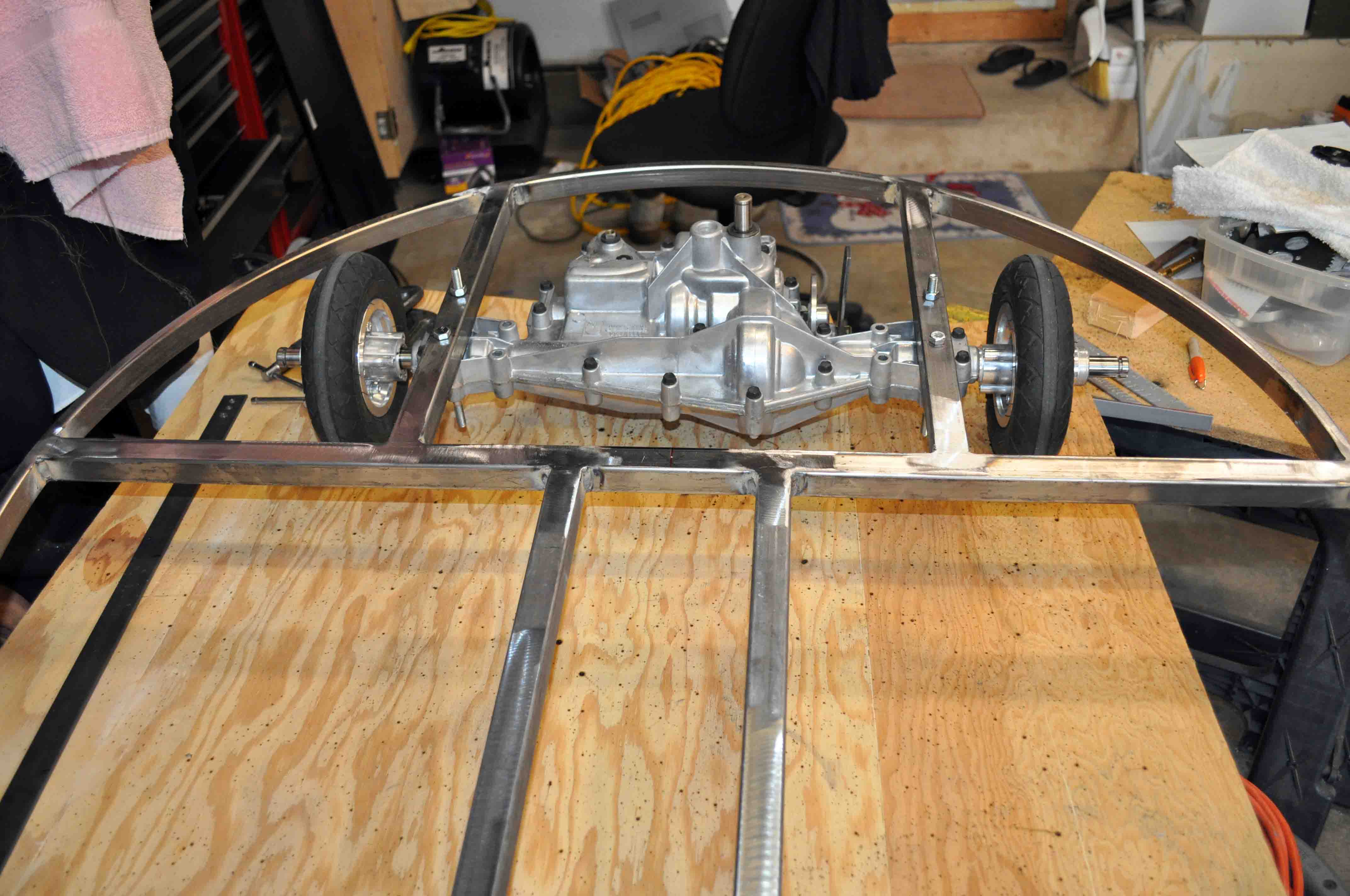
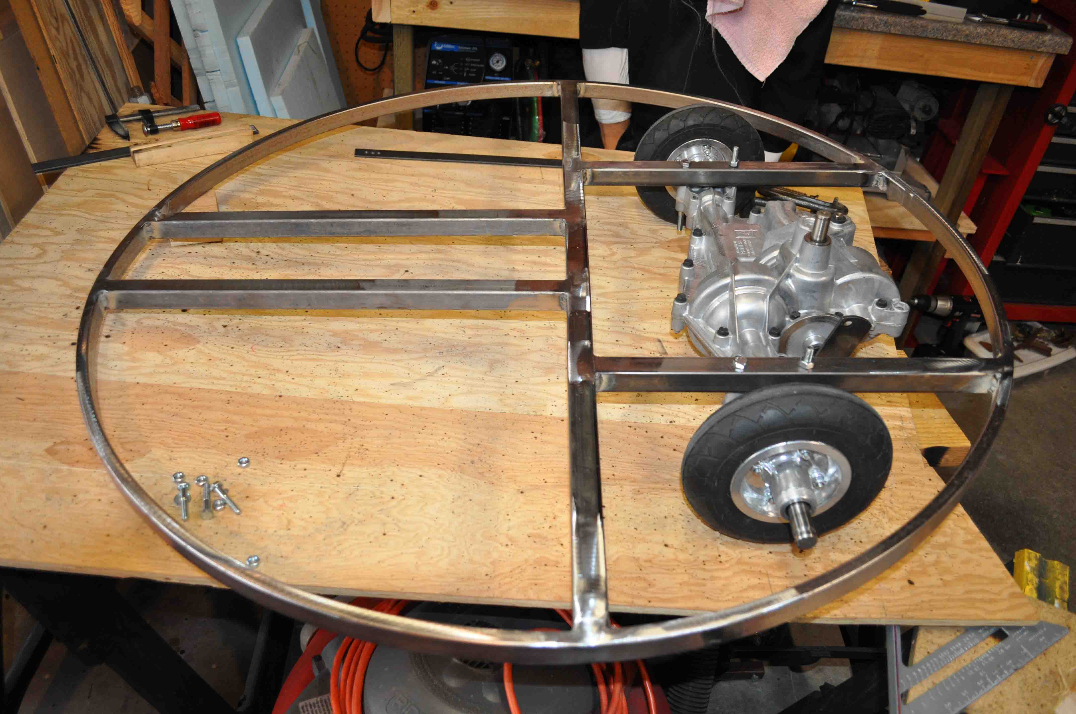
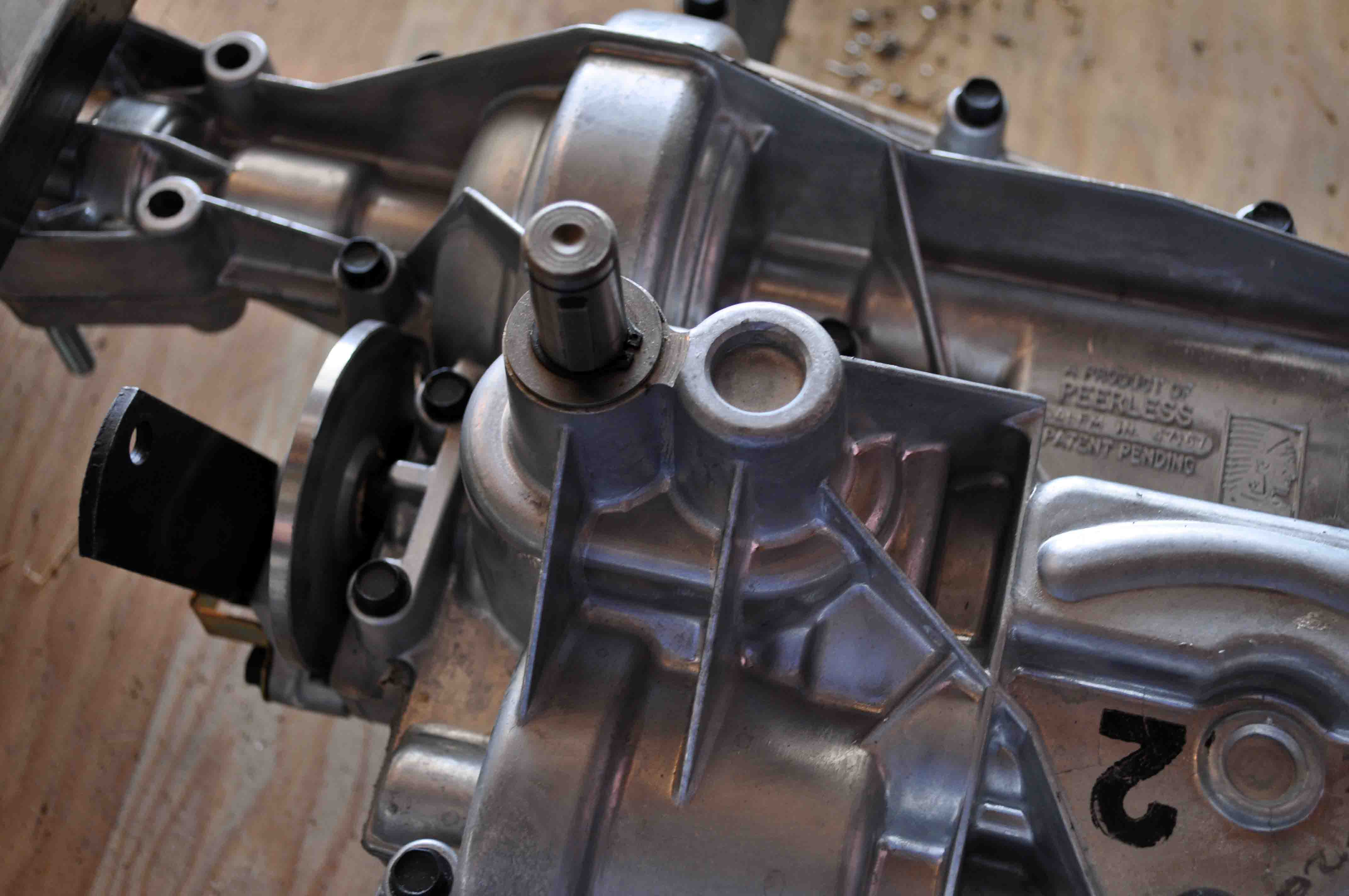
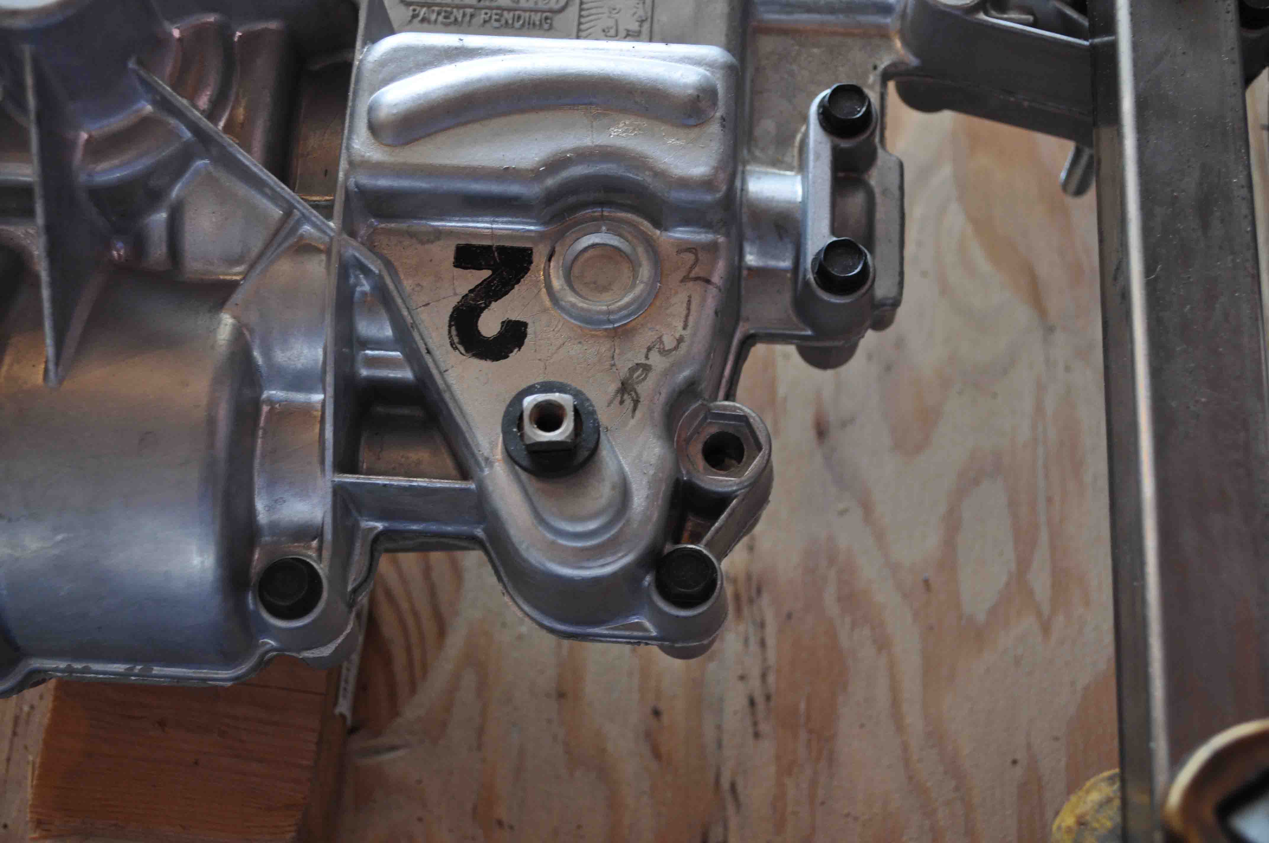
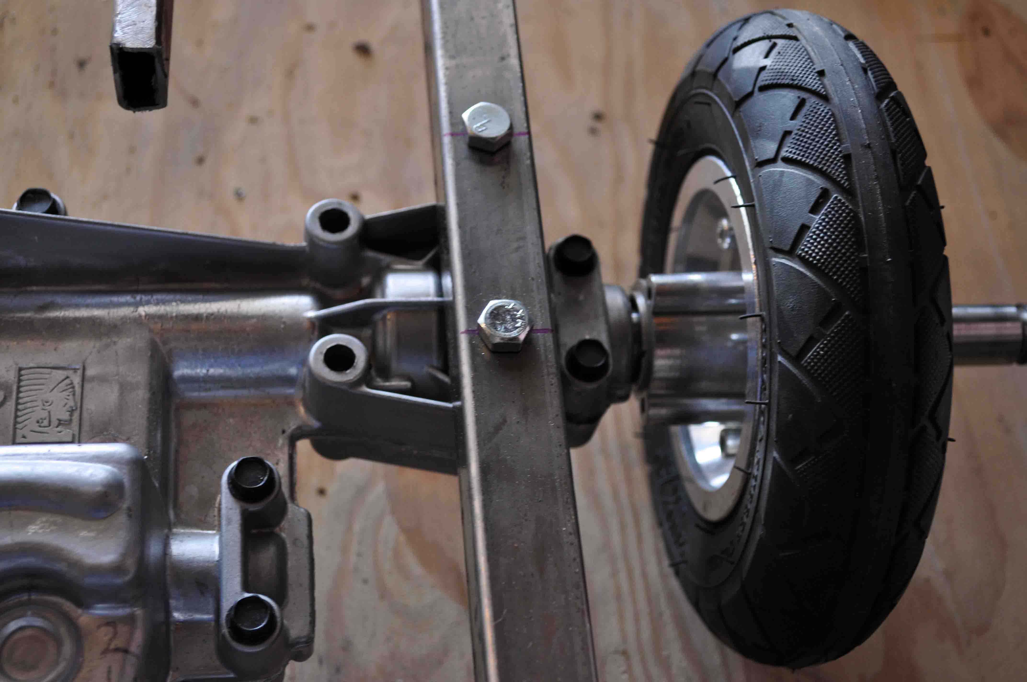
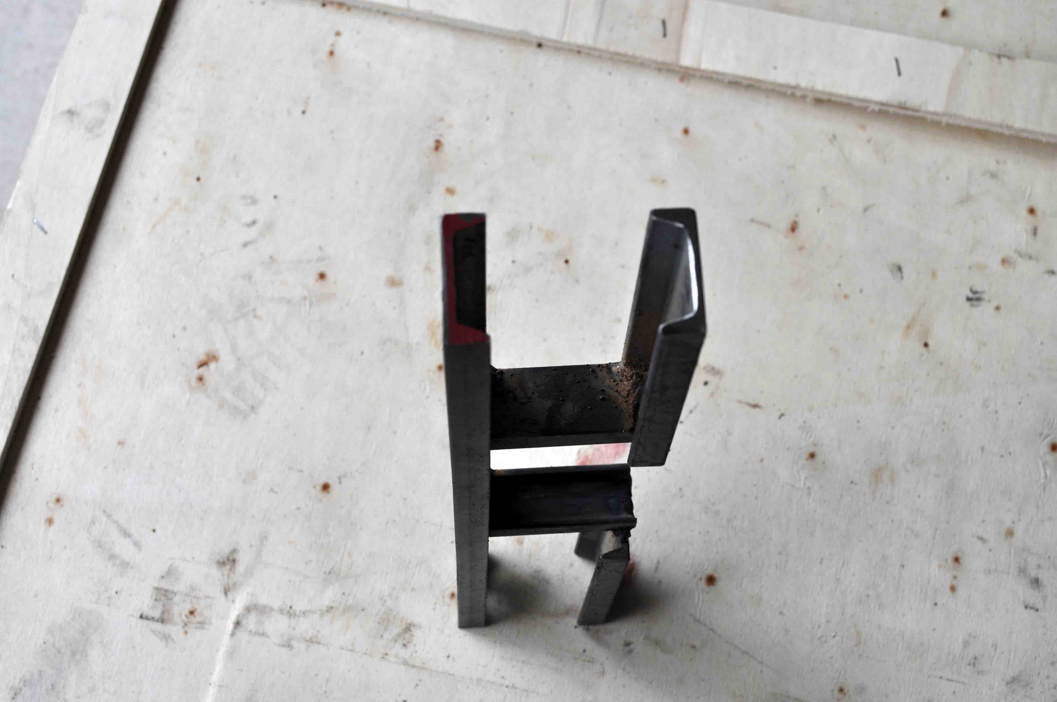
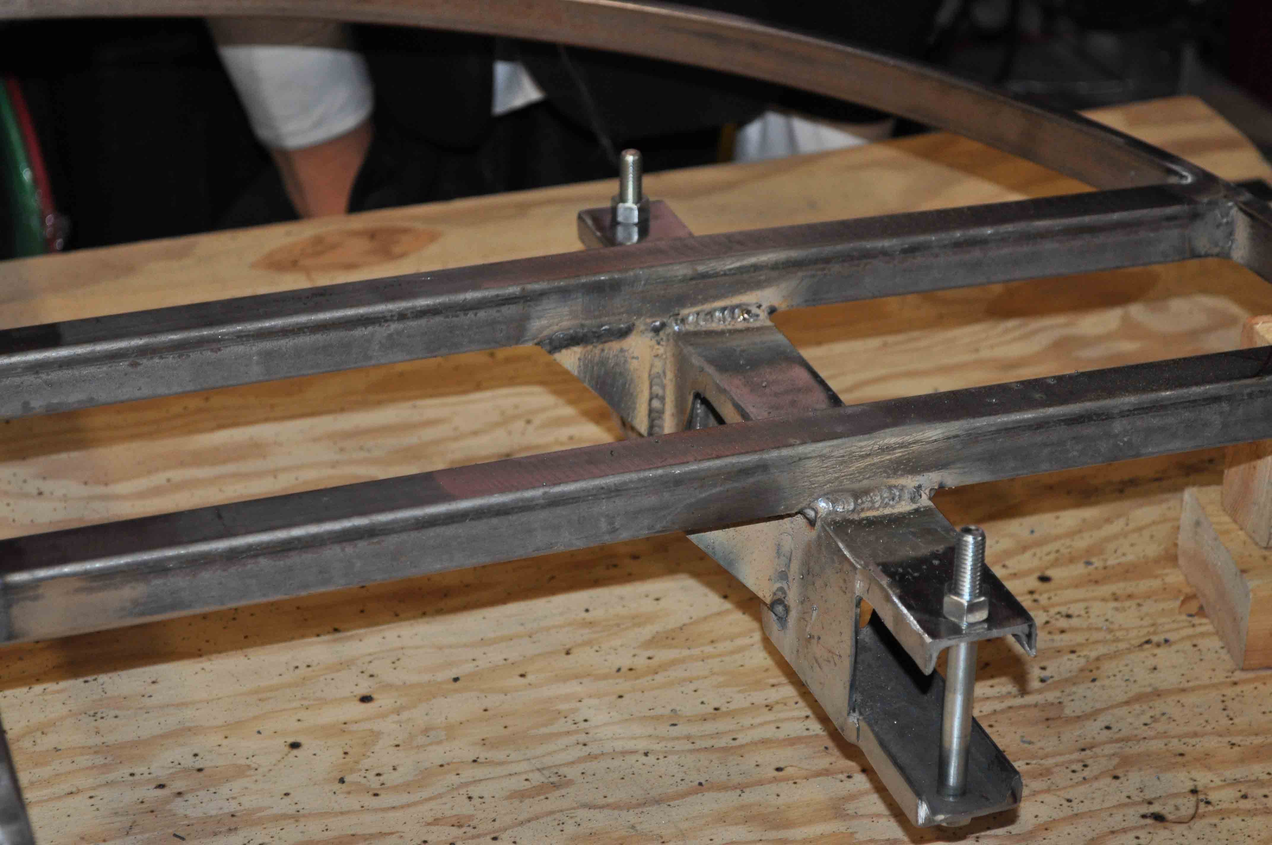
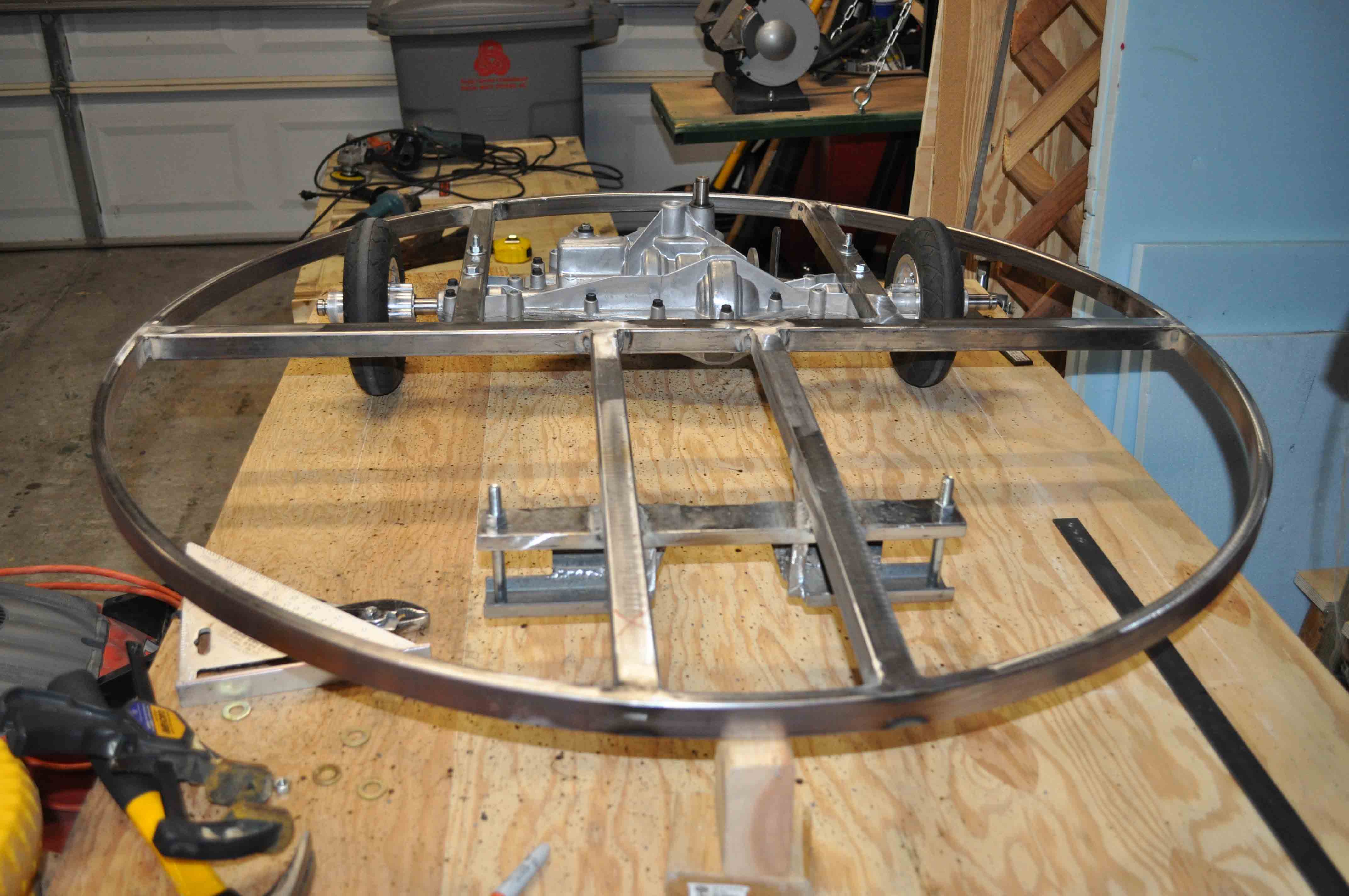
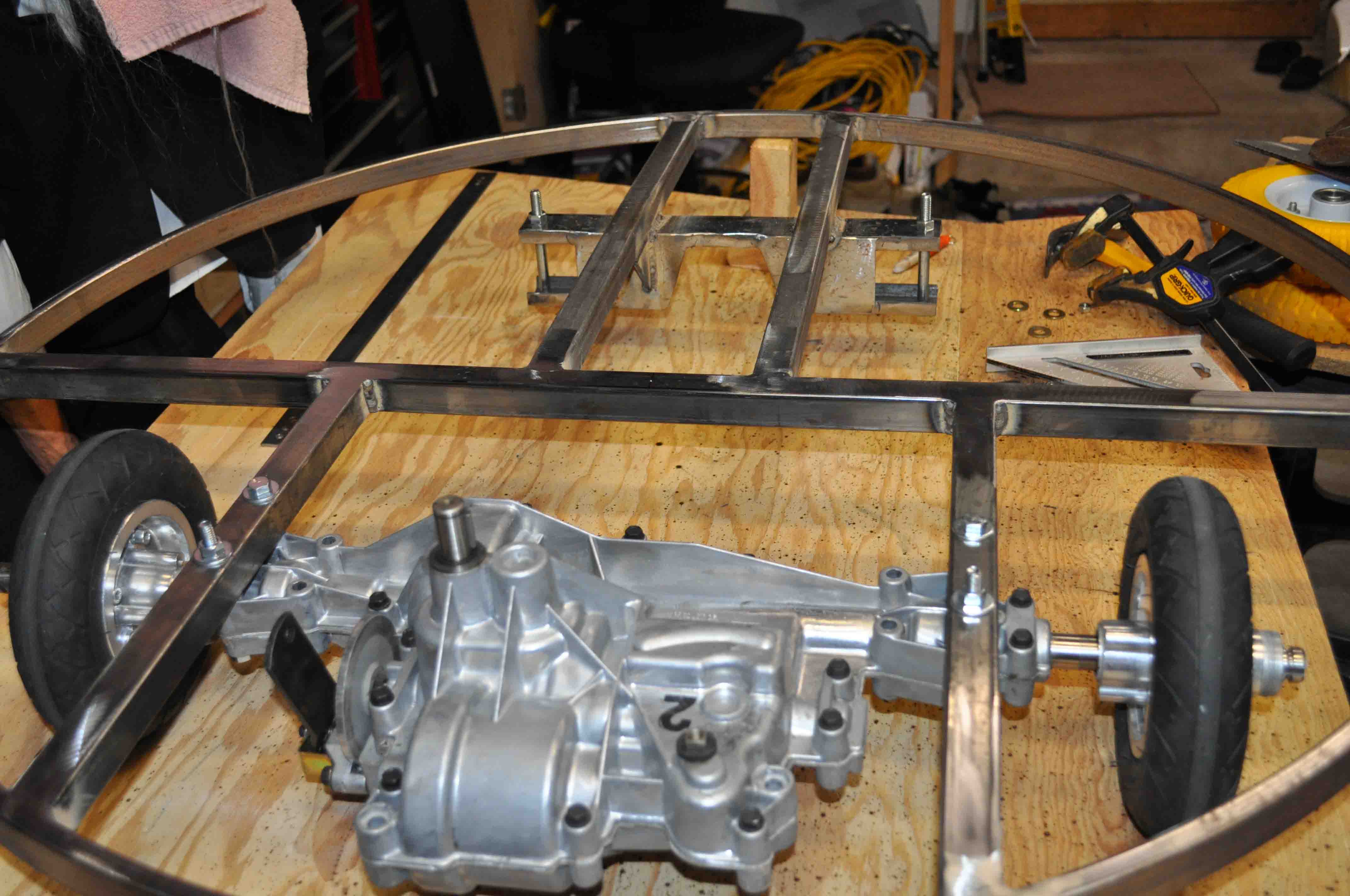
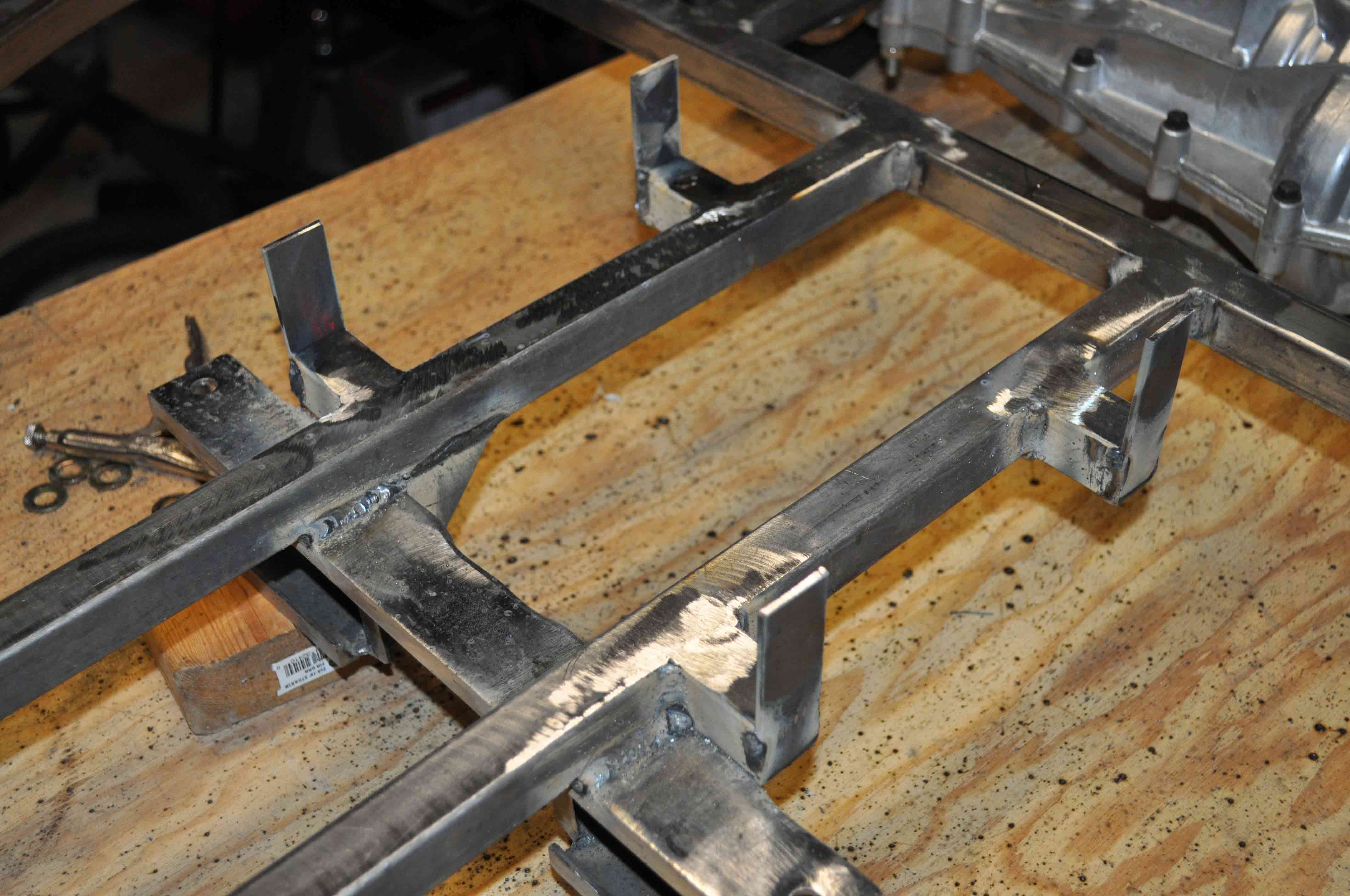
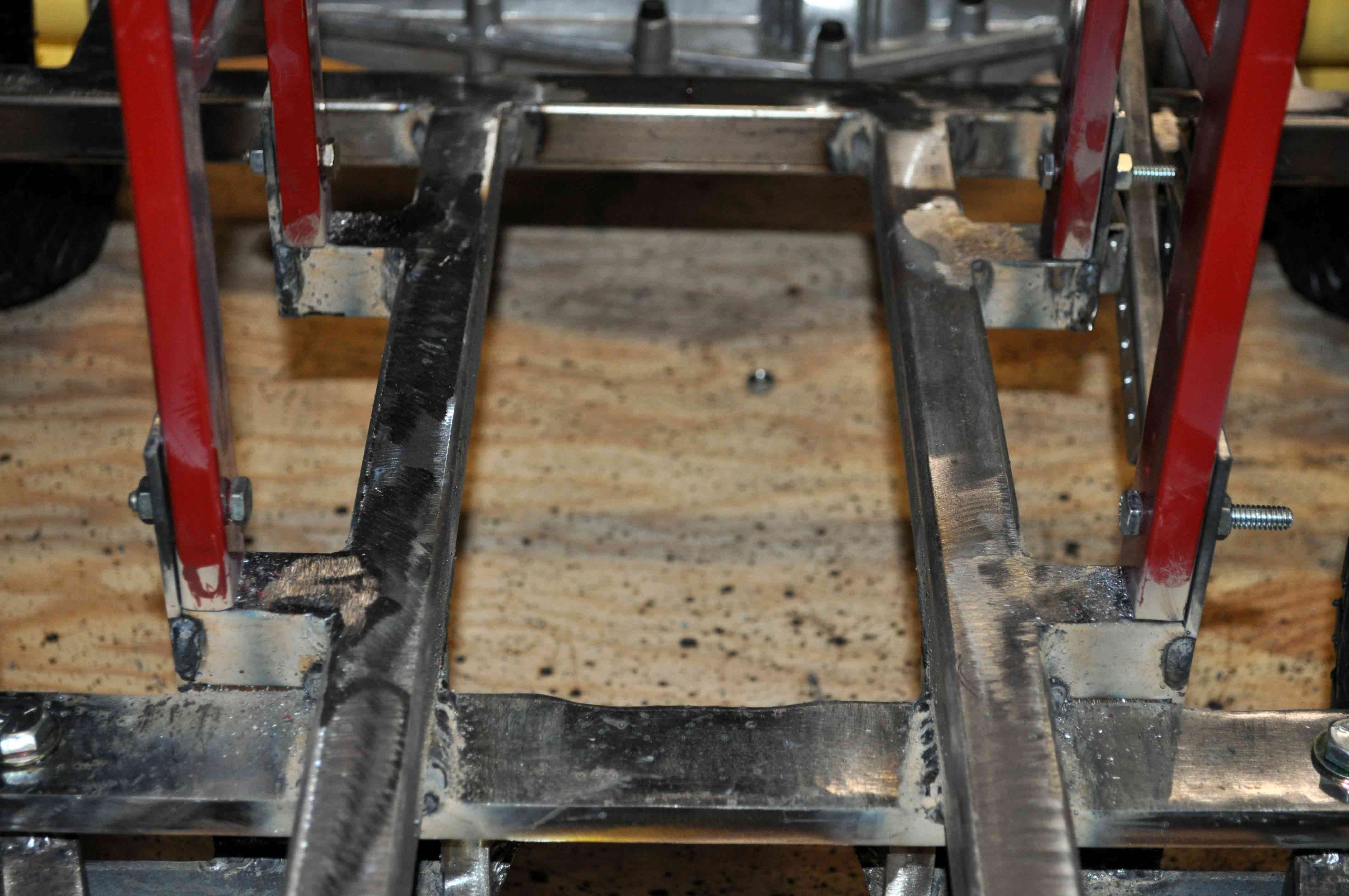
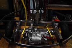
Ok, while we are at a working stage at this point and the live axle is a fair plan. However I found some new surplus transaxles that are commonly used in riding lawn mowers with two forward gears, a reverse gear, intragrated disc brake, and a differential that I just could not pass on for the price so I am now cutting out the existing drive train and refabricating the frame to accommodate the peerless transaxle.
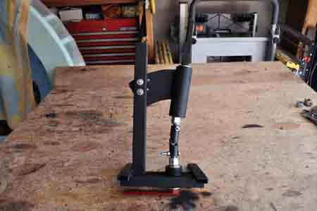
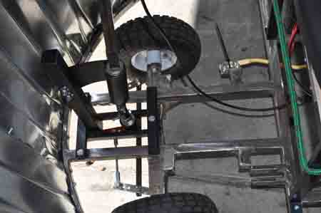
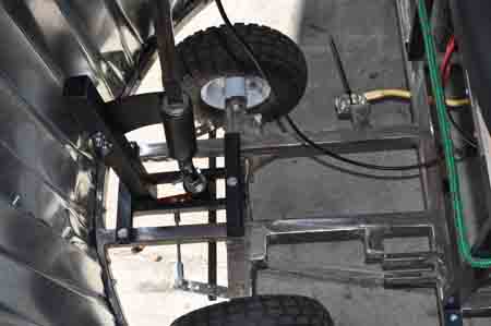
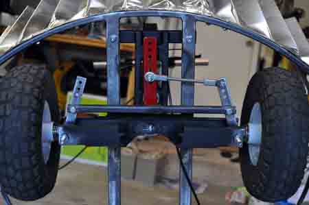
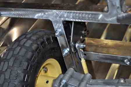
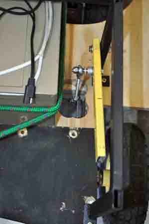
With the new transaxle I have also decided to go with a 10 inch wheel instead of the original 8 inch to get a little more clearance for the transaxle. This little change rippled through and I had to lower the steering assembly. With the steering comments cut off the frame I found it irresistible to make some changes allowing for a tighter turning radius
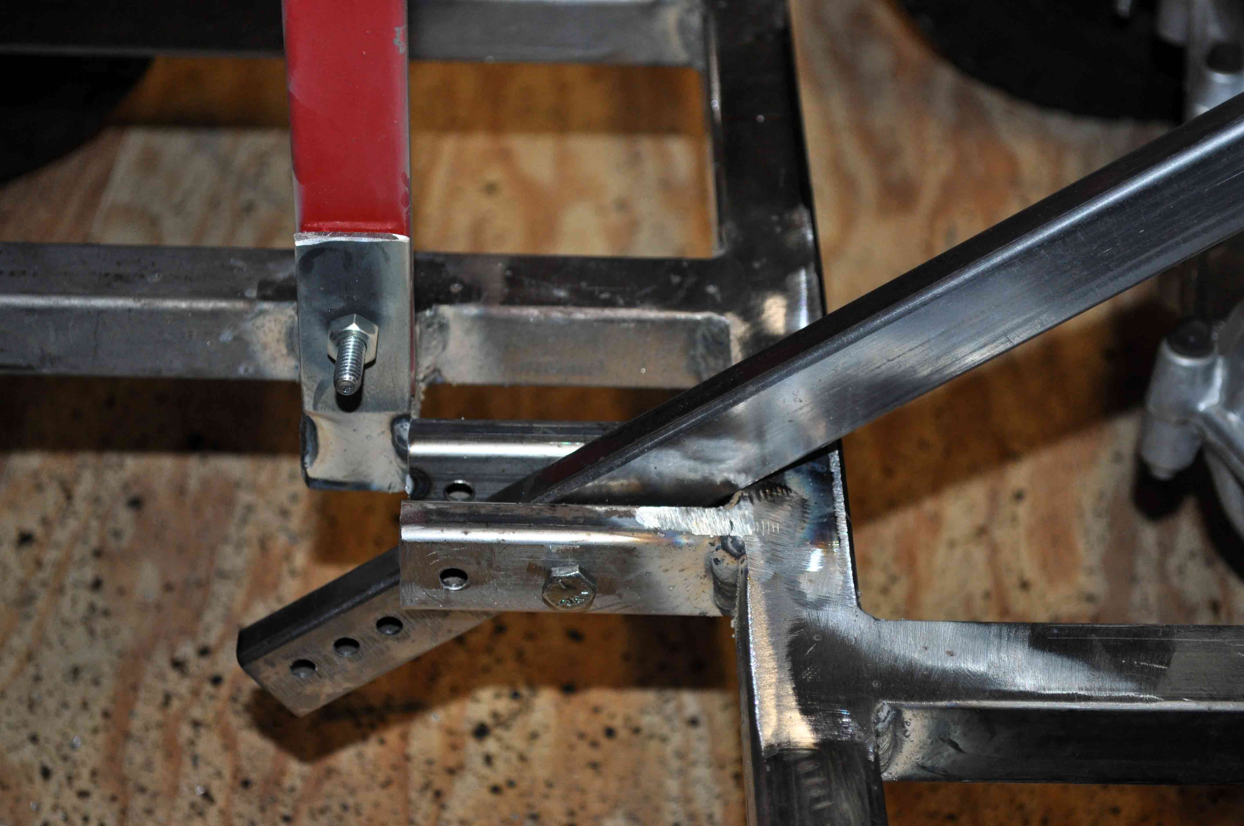
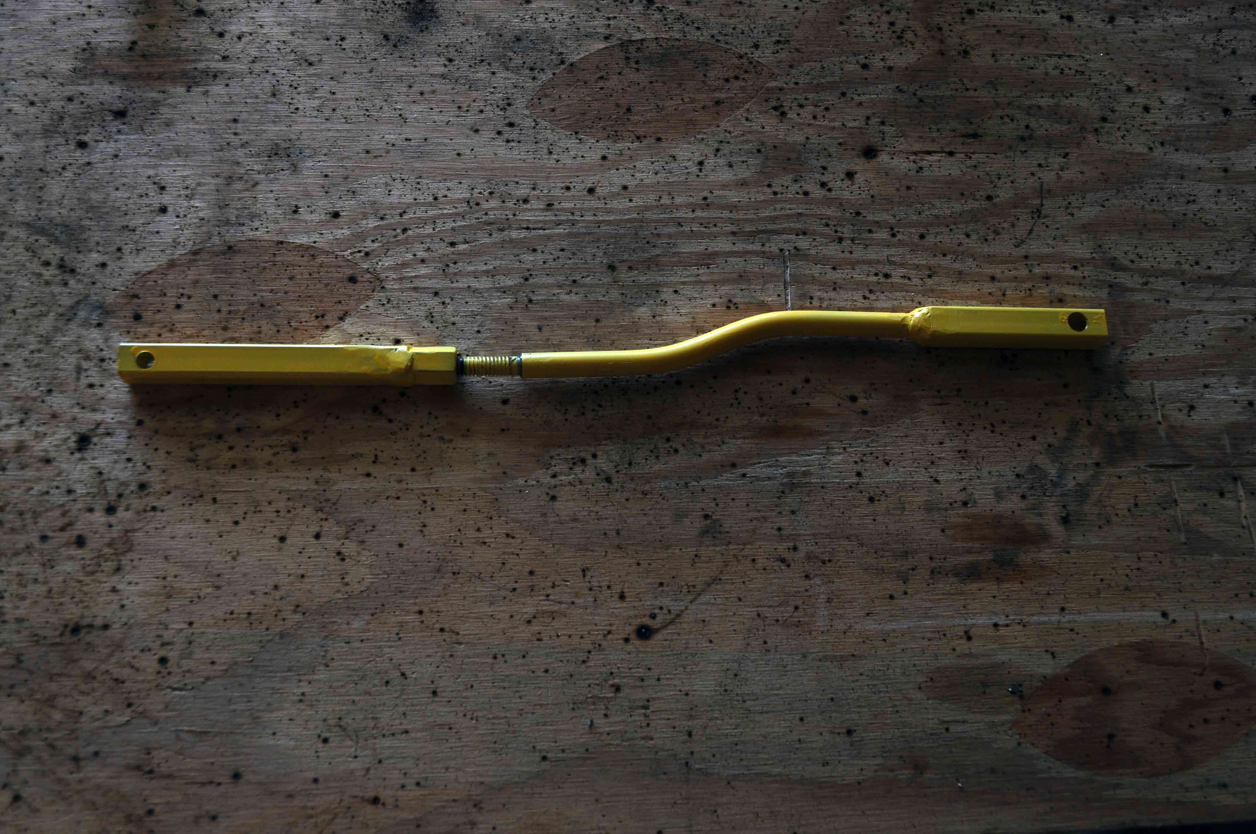
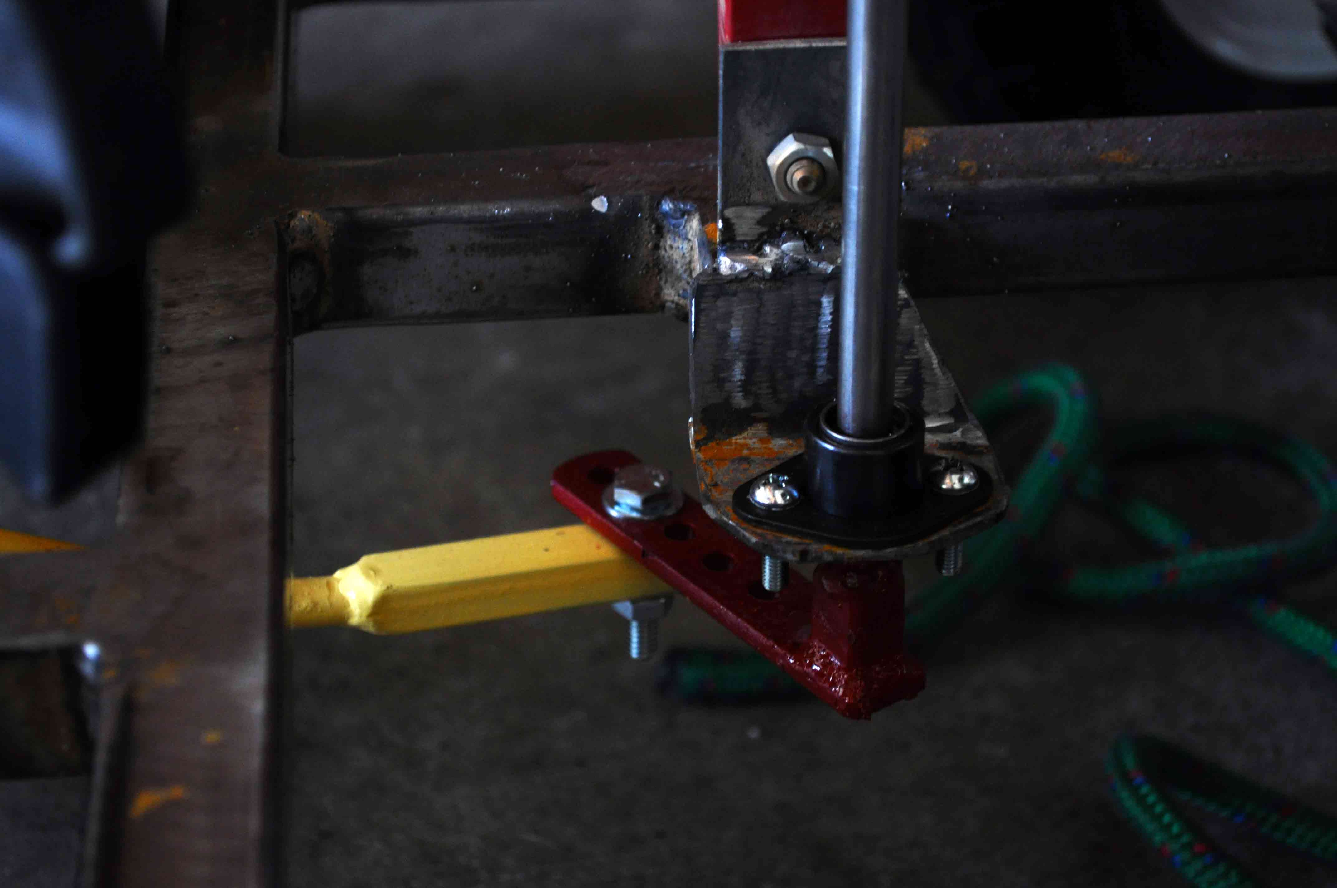
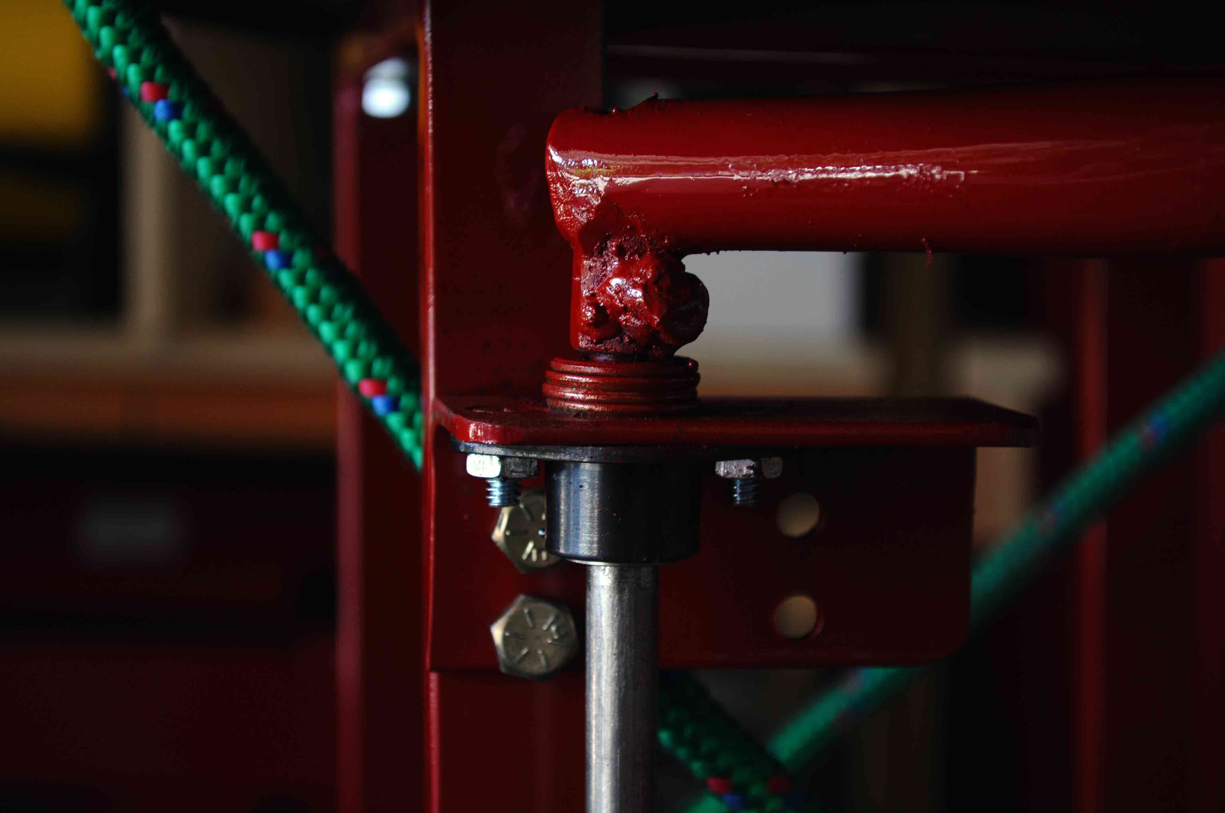
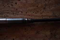
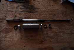
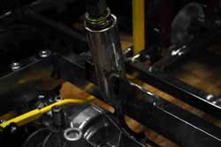
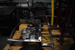
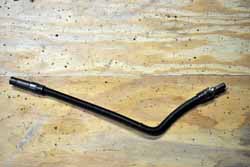
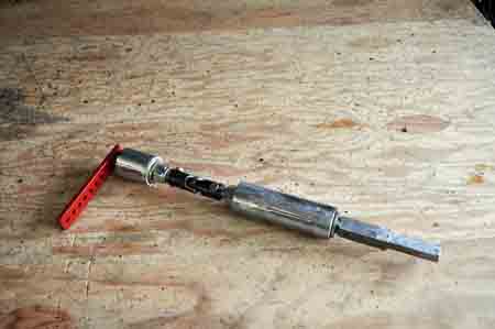
The flex shaft seemed like an eleiquent solution to the direction change and limited clearance for the steering linkage. However I had some concerns about the strengh of the shaft and ended up correct as I tied the flex shaft into a knot while trying to test drive the car. Next up will be a set of U-joints, though the extream 90 degree angle may prove to be a problem.
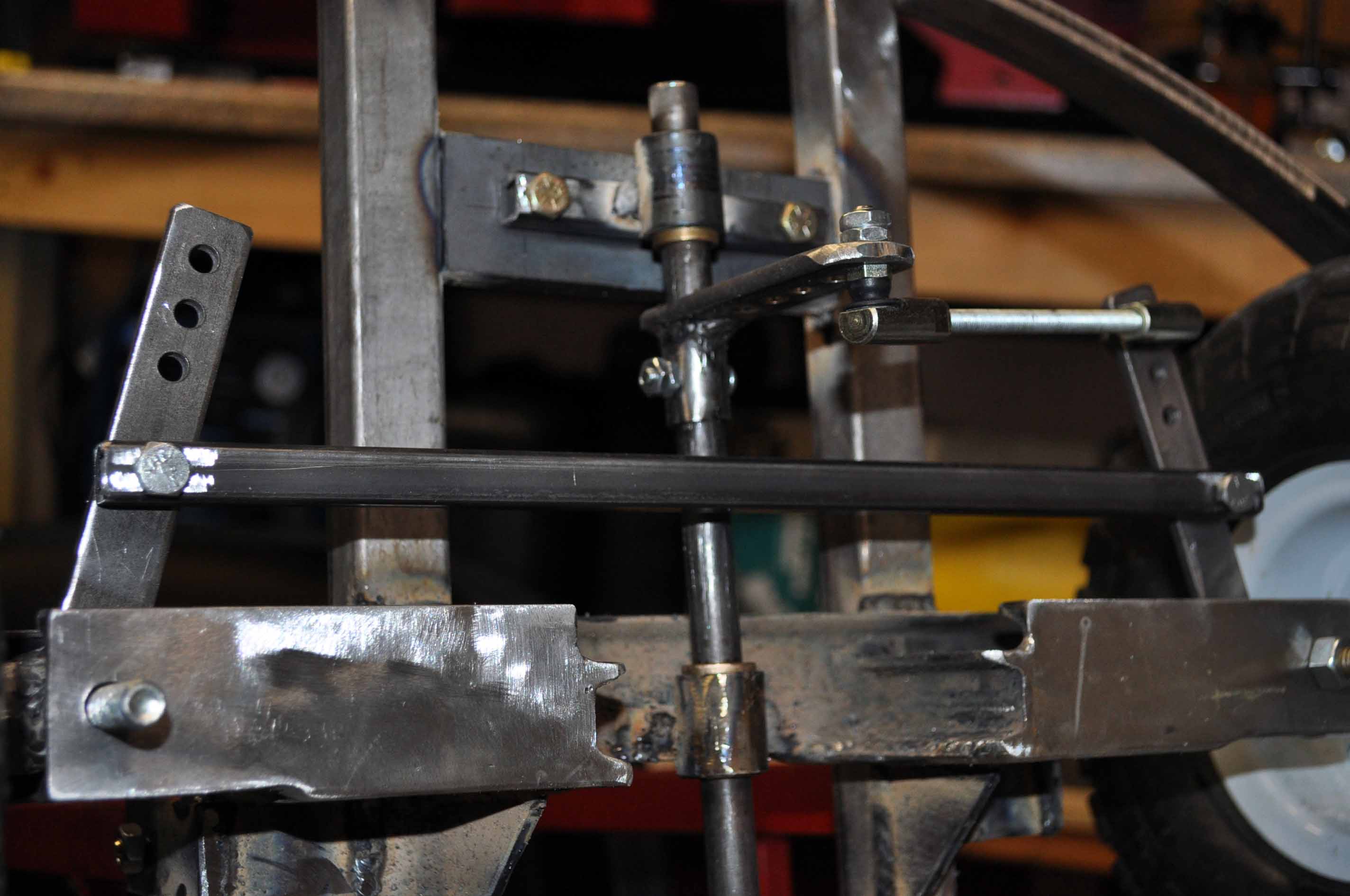
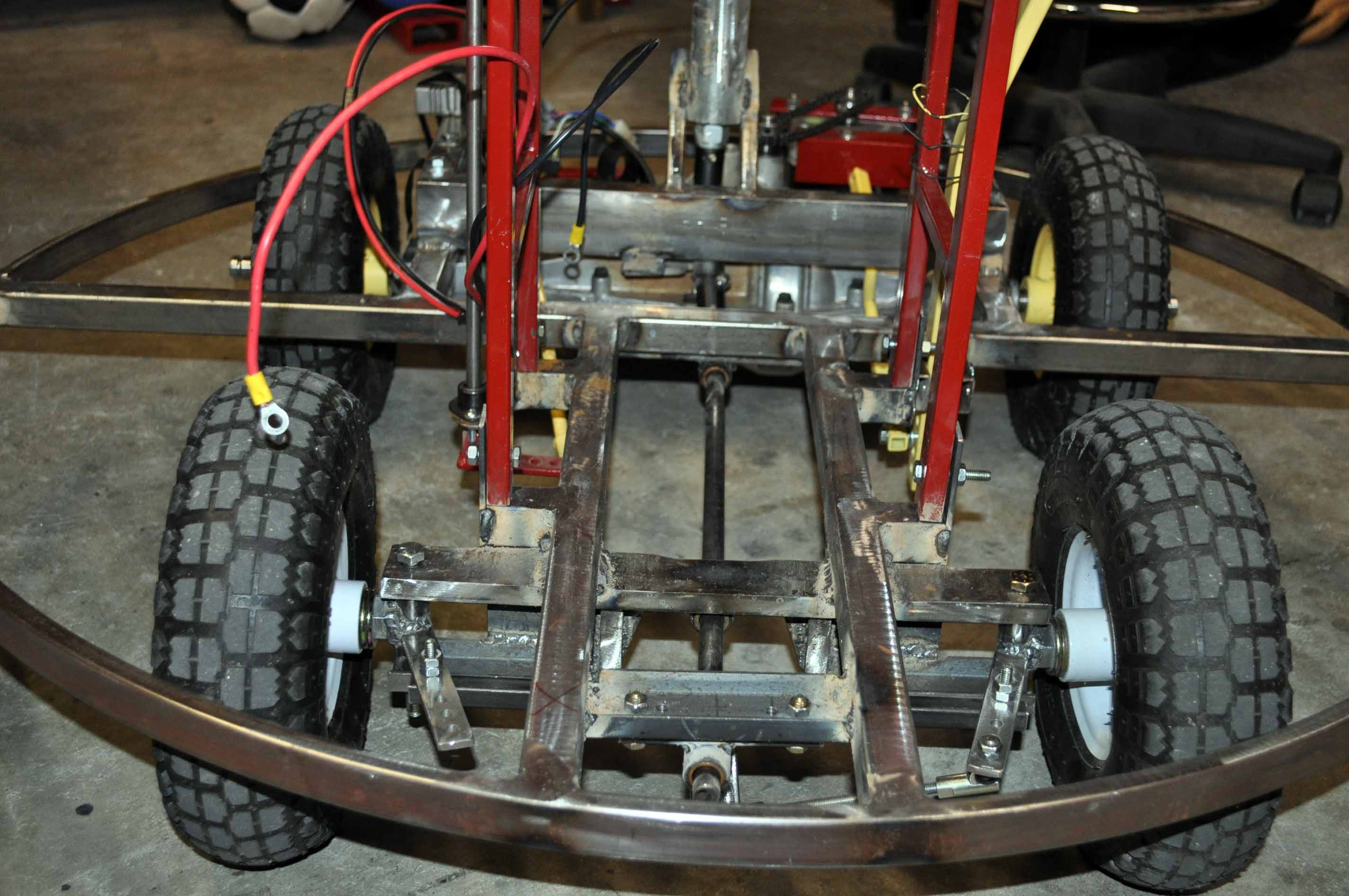
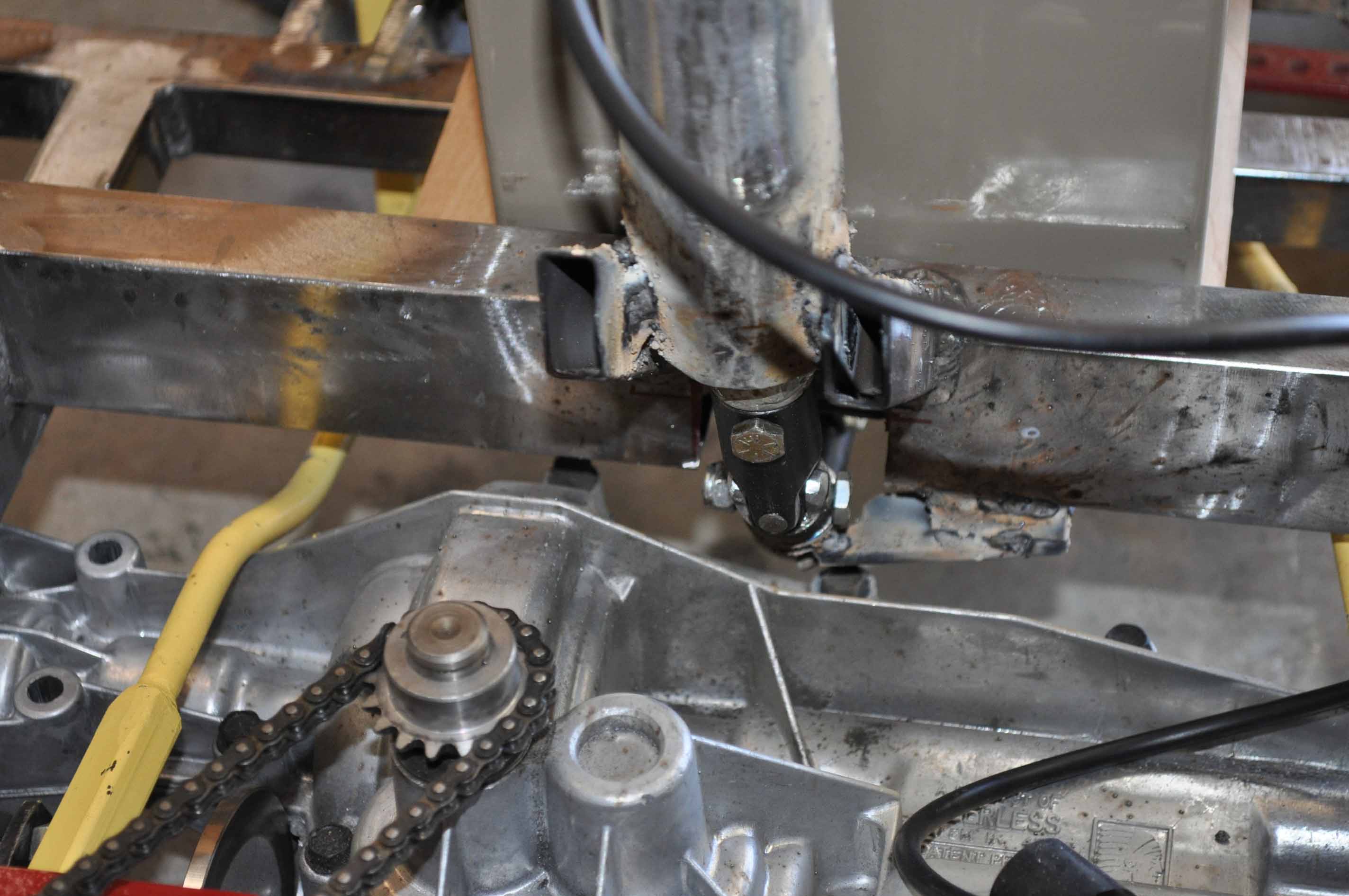
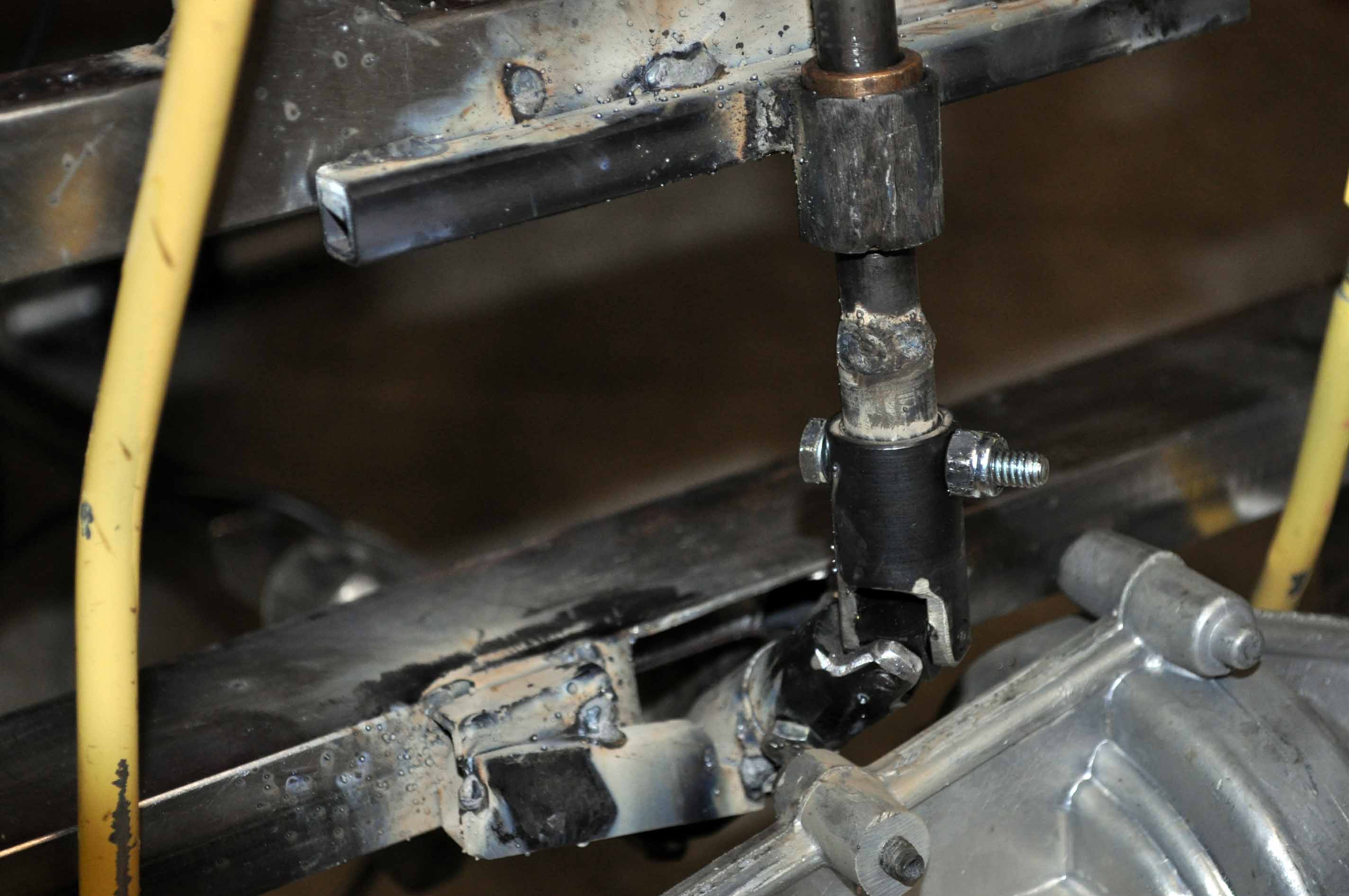
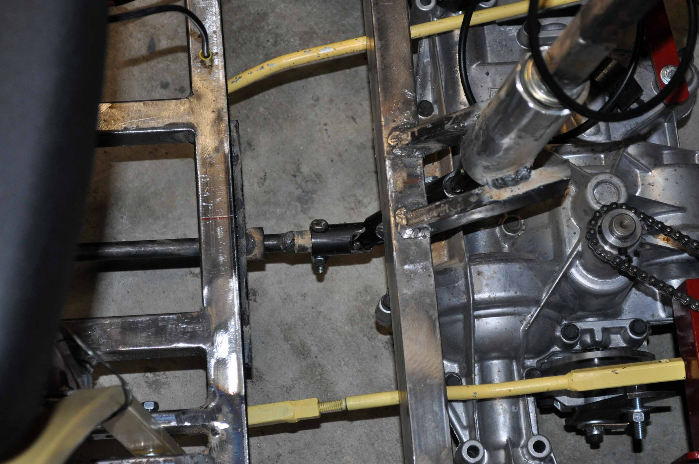
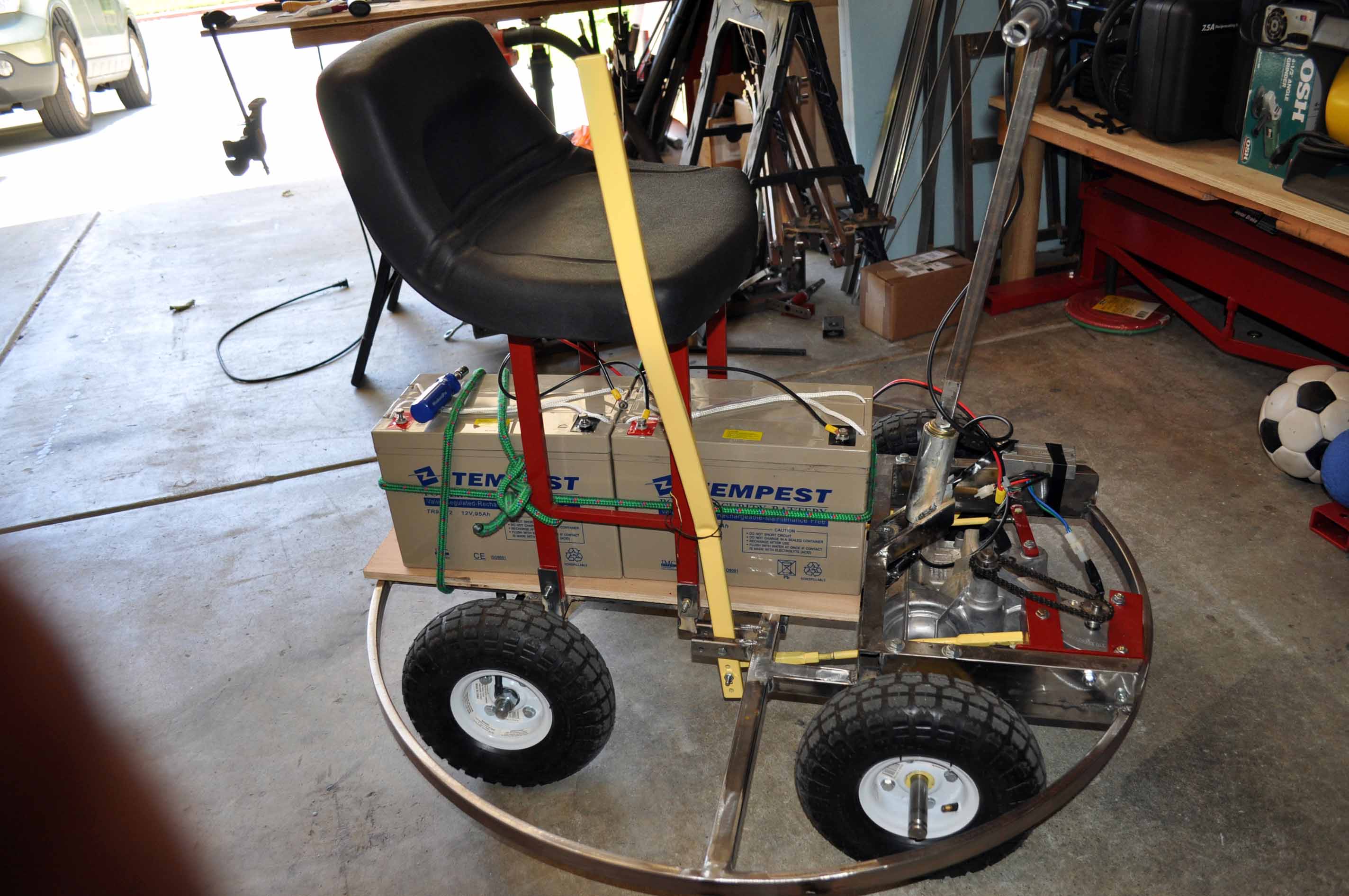
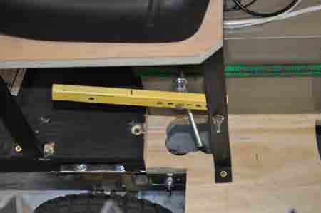
Well the U-joints are in but after having to grind down the fingers a little to get the from the 30 degree max angle to the 45 degrees I need I ended up adding some additional play or slop into the steering. To help solve this I added a supported bushing to the short shaft betweent he two U-joints. I should also not that this extra angle added stress to the U-joint pins causing the stock ones to snap. As a result I have turned a new set out of a higher grade steel and all seems well in initial testing. Now to go back and clean up some of the steering parts and finish weld them.
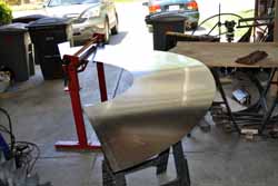
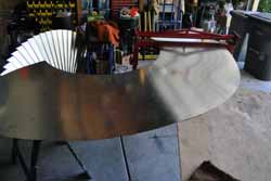
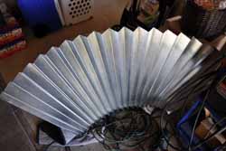
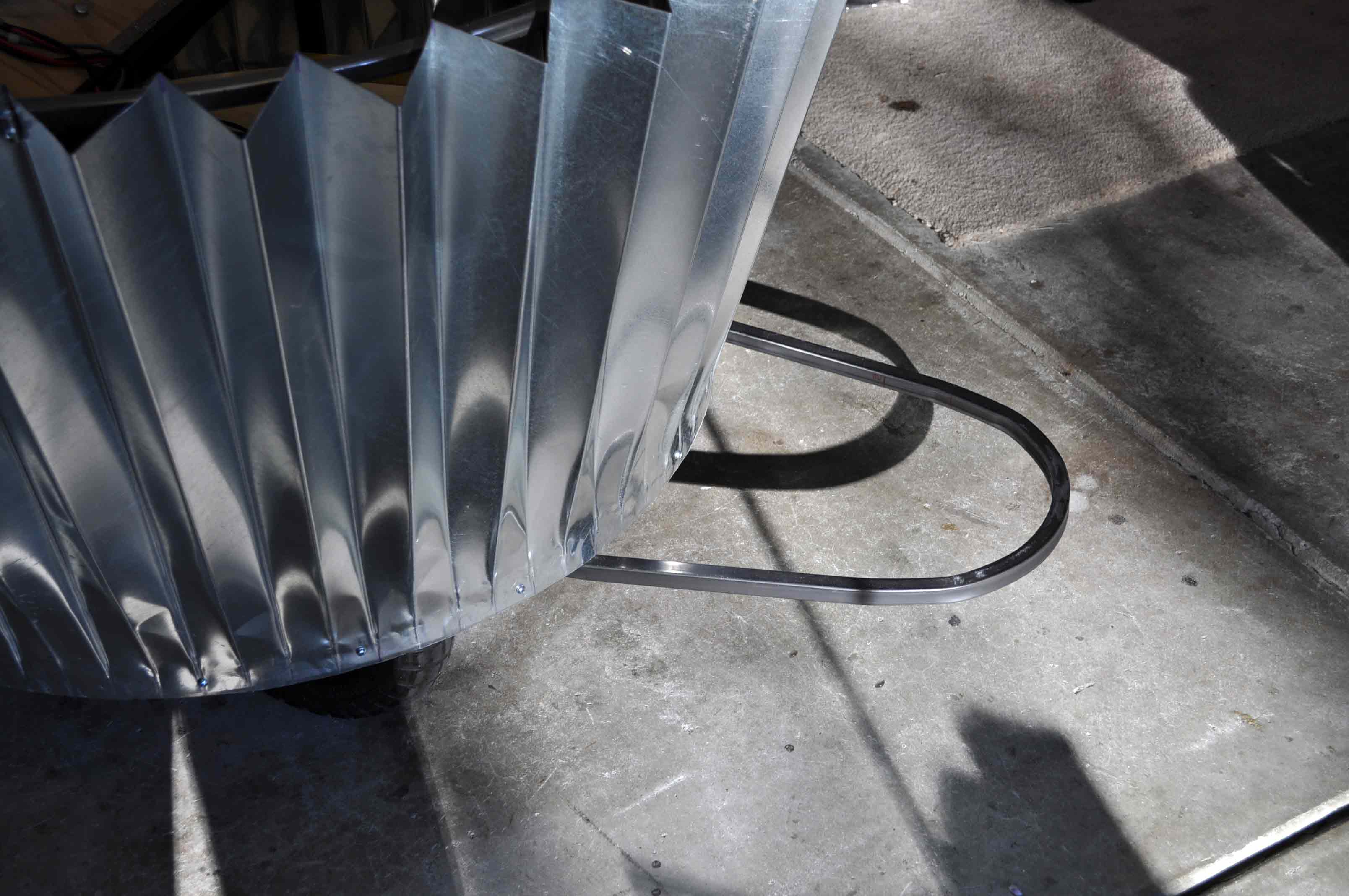
The sheet metal arcs were cut from two 4 x 8 sheets of 24 ga galvanized metal. I used a metal break to create the nice bends of the fan fold. I would plan on getting a little help with this step, as pulling the metal in and out of the break and flipping it over for all the bends gets tricky with only a single person.
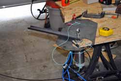
After compleating the folds, I needed to flatten out the folds along the bottom. To do this I used a 3 inch bore pneumatic cylinder I had floating around and mouned it in a piece of plywood I have been working ontop of. To the cylinder rod I mounted a peice of scrap steel channel. Then placed the folded sheet metal under the channel and applied 120 psi of air to flatten each bend. To finish off flattening the bottom I used some wood blocks and a 3 pound hammer.
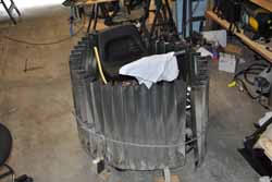
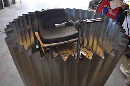
mock up if the muffin tin.
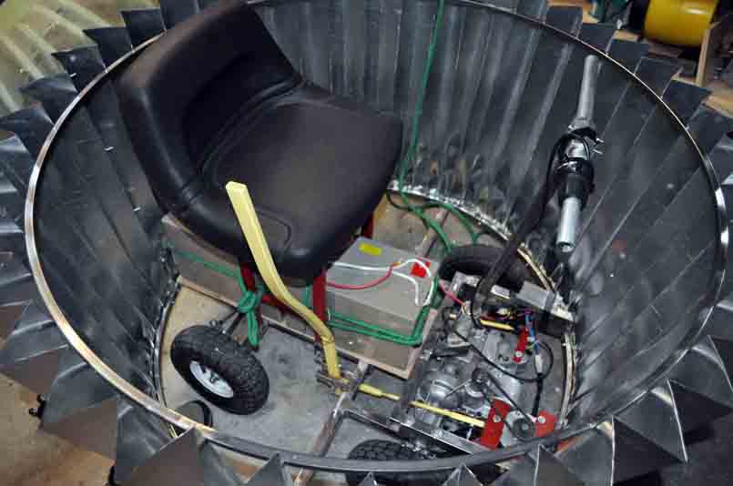
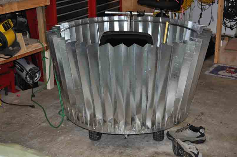
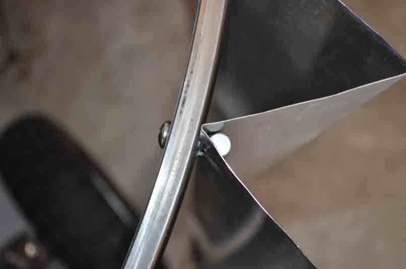
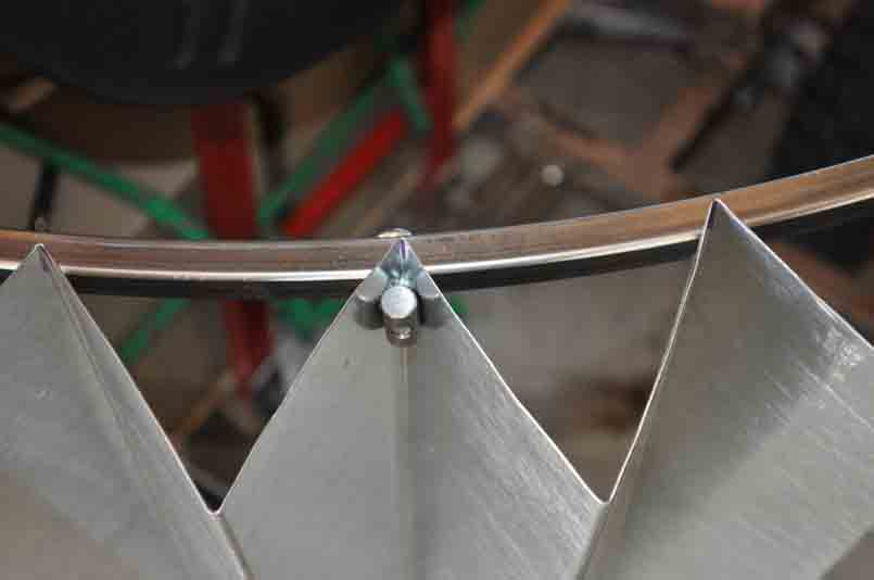
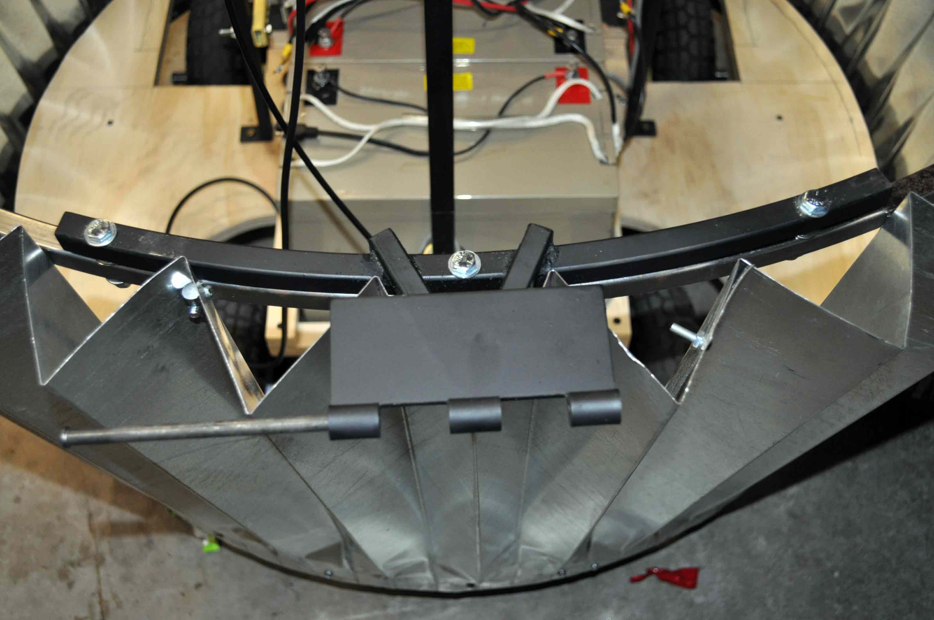
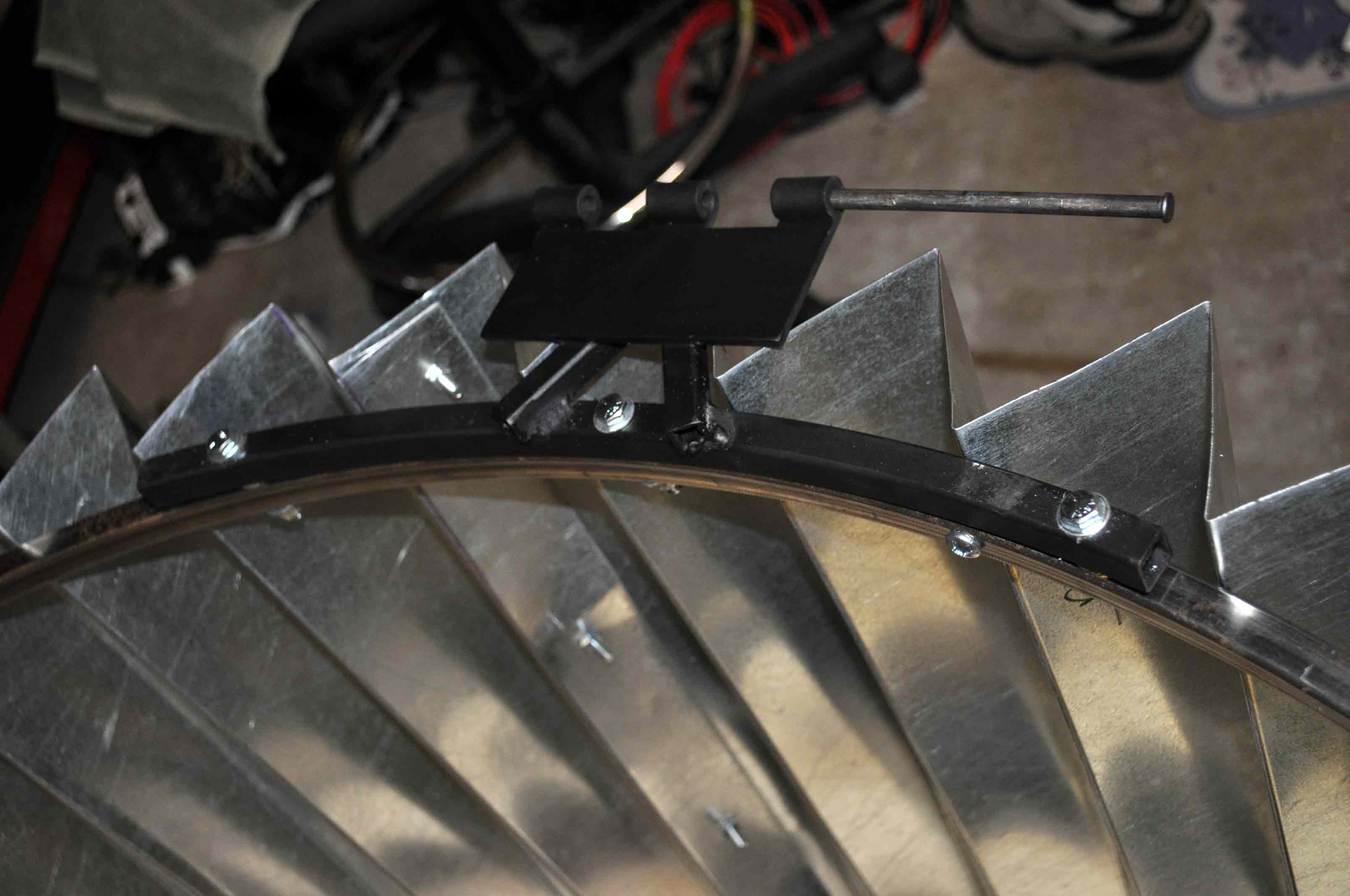
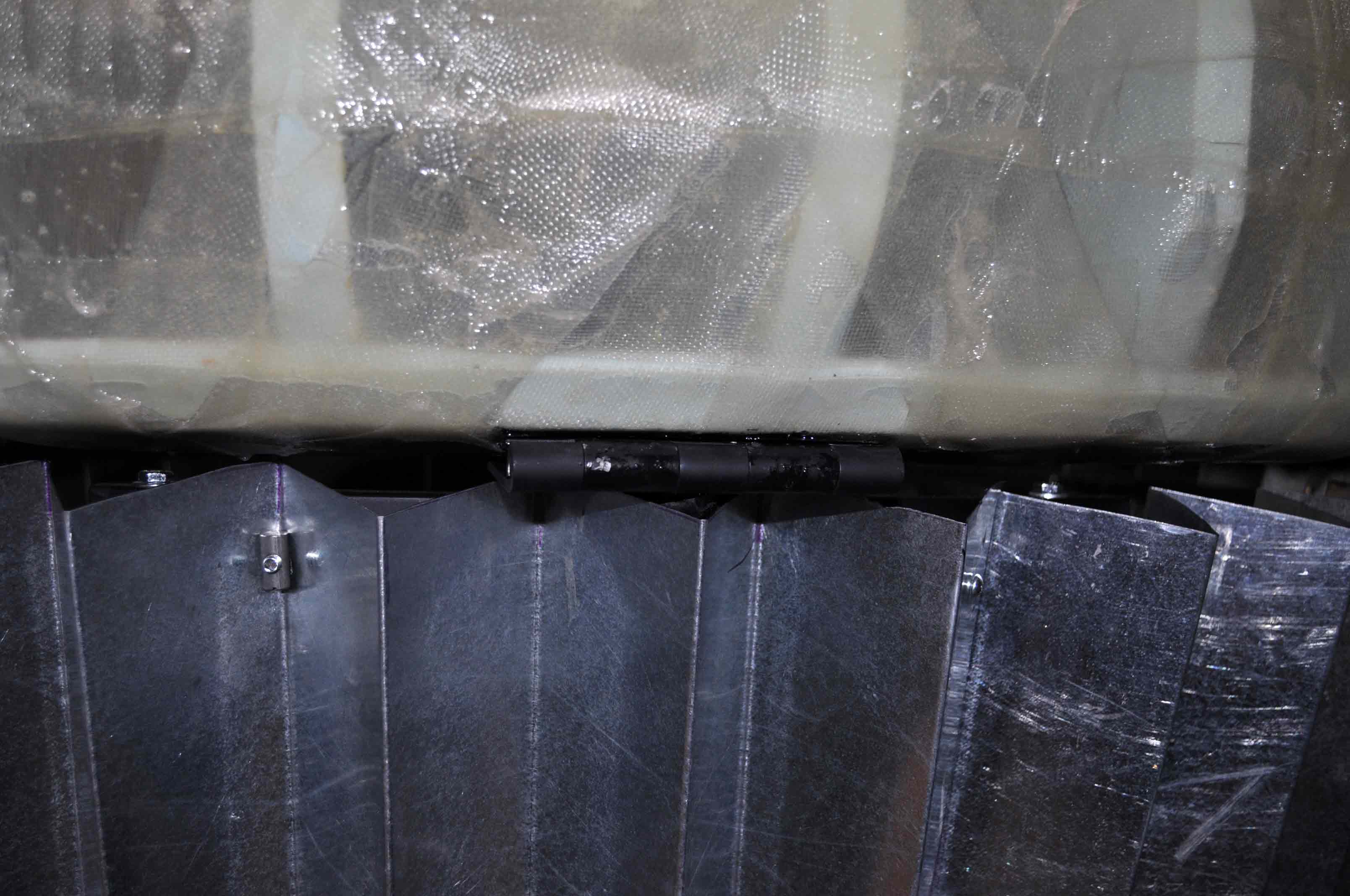
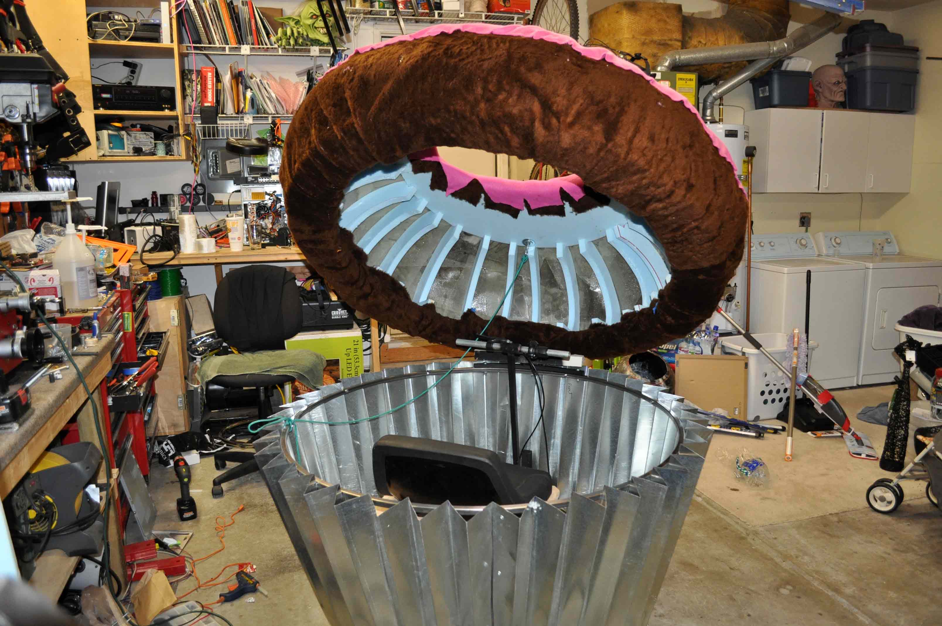
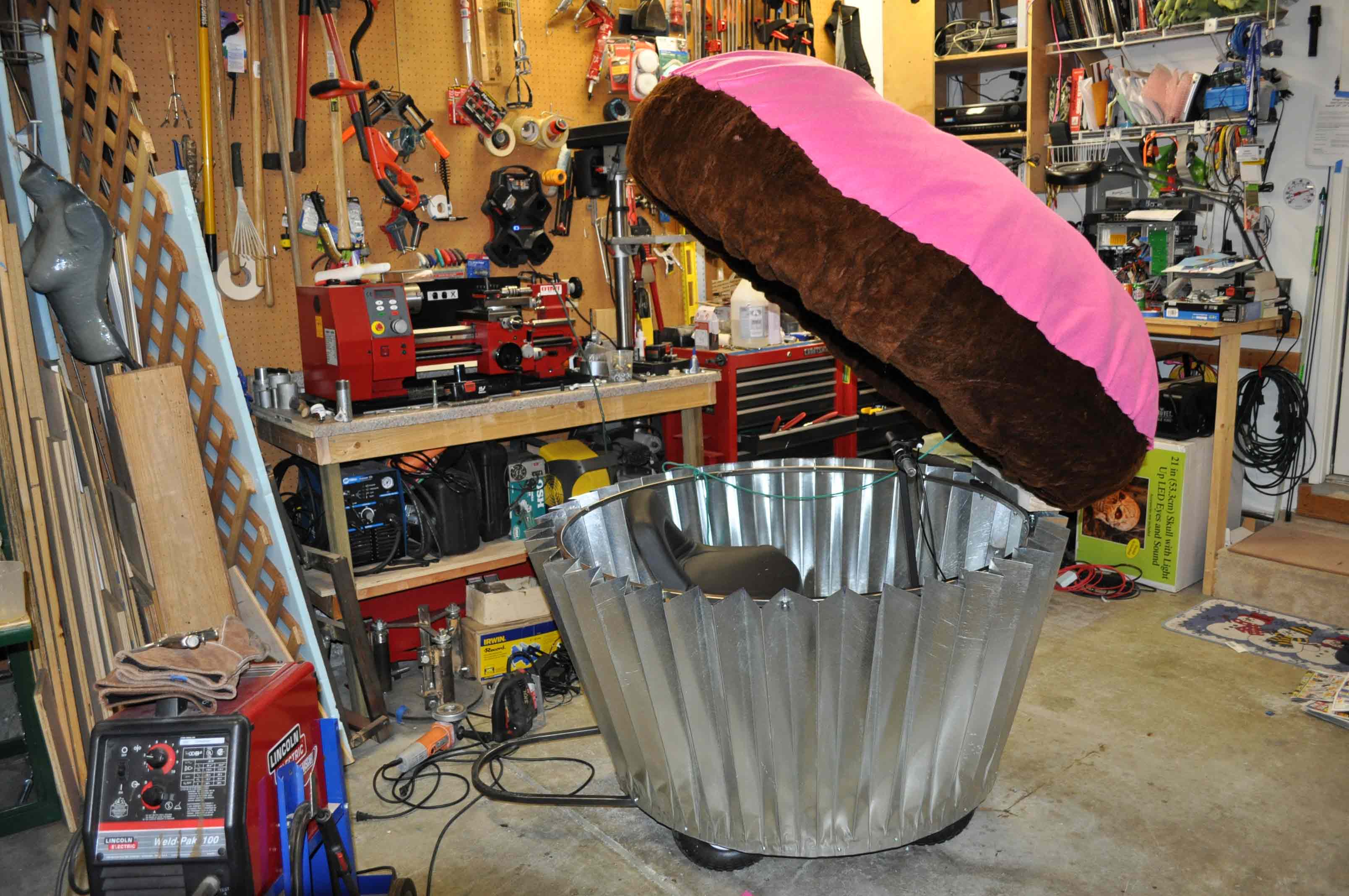
Muffin tin in place and an upper 1/2 inch square tube ring bolted to the upper edge of the tin for strength as well as providing a place to mount the hinge assambily for the lid.
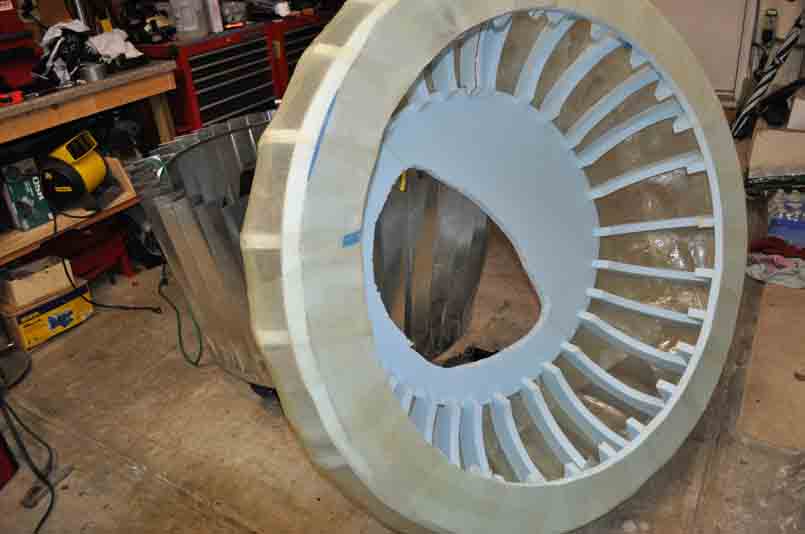
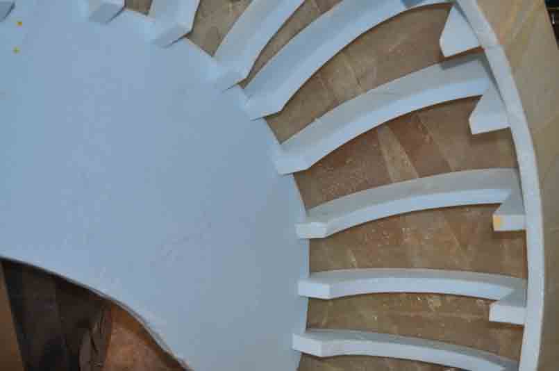
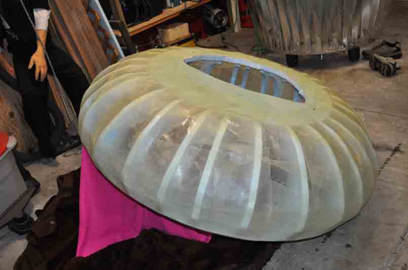
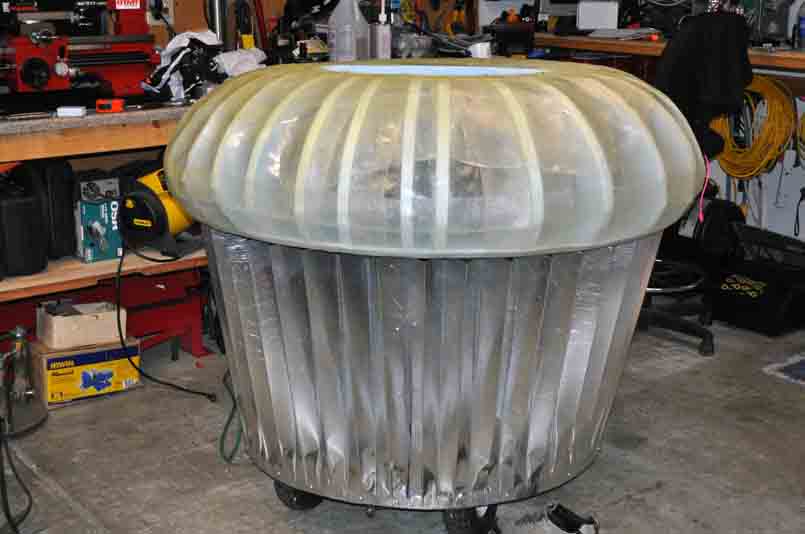
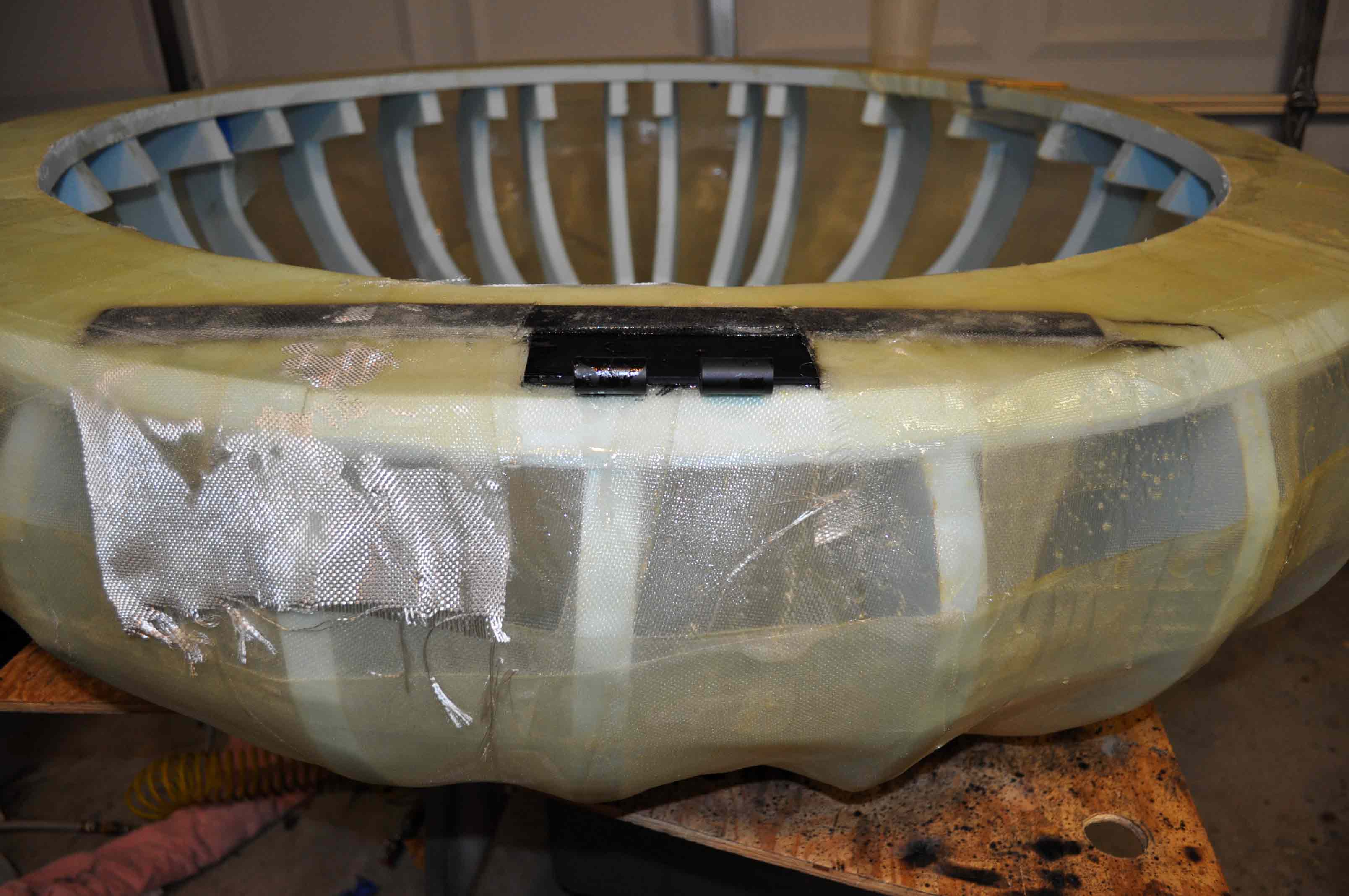
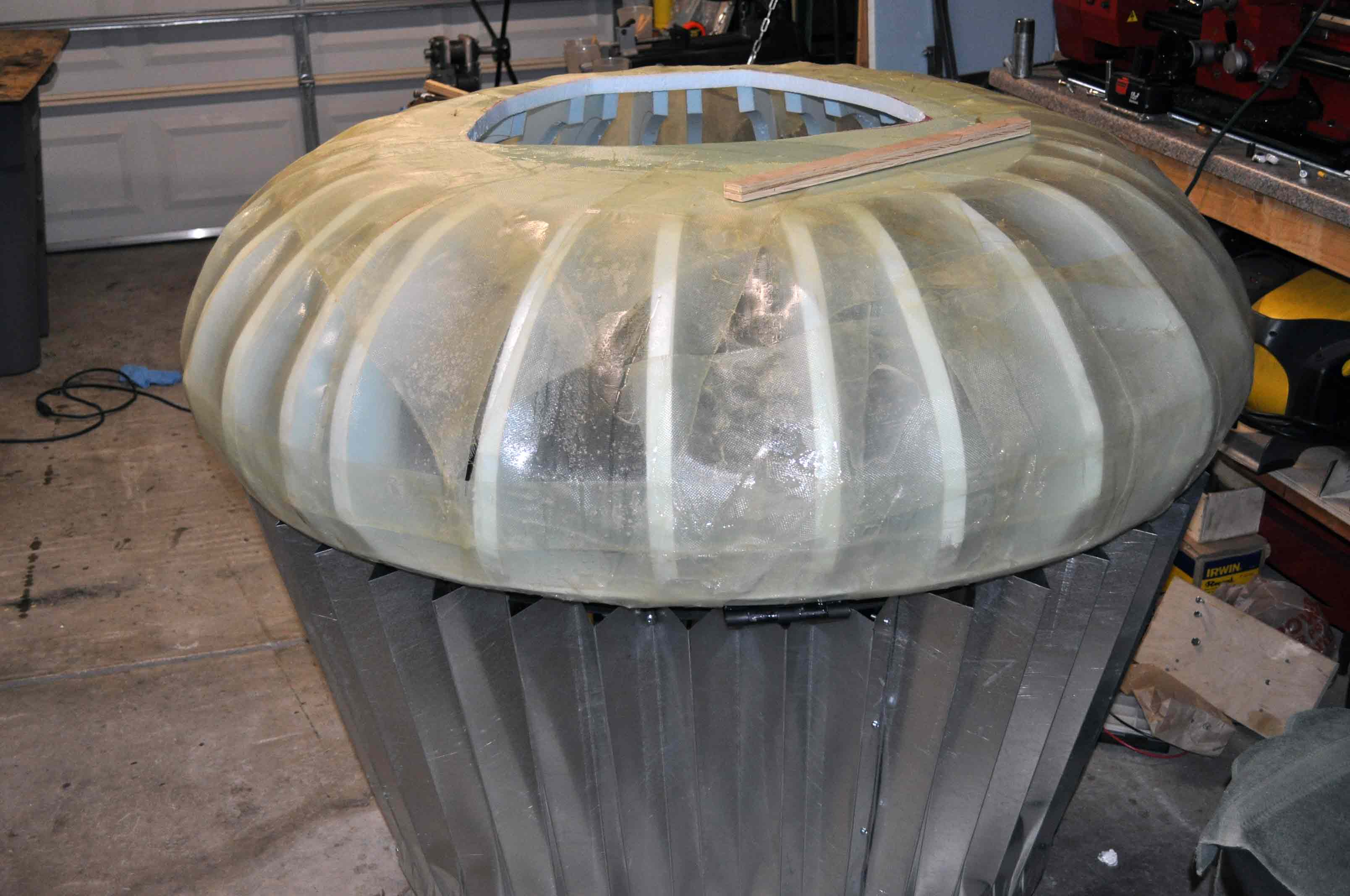
Frame of the muffin top was made from 1 inch thick eps foam cut down into ribs and circular parts. This frame was then covered in two to three layers of glass cloth and epoxy resin. a few spots have been reinforced in preparation of attaching a hinging assembly later.
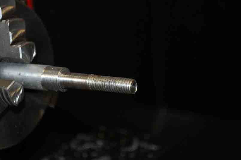
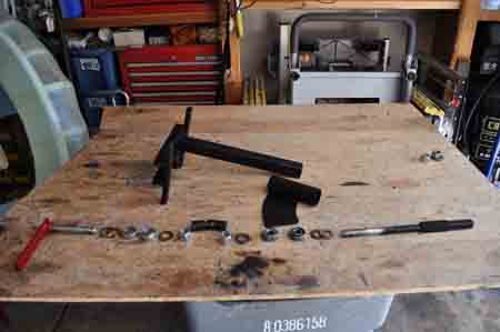
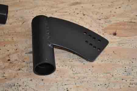
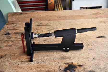
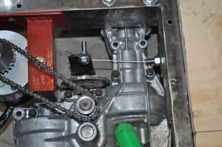
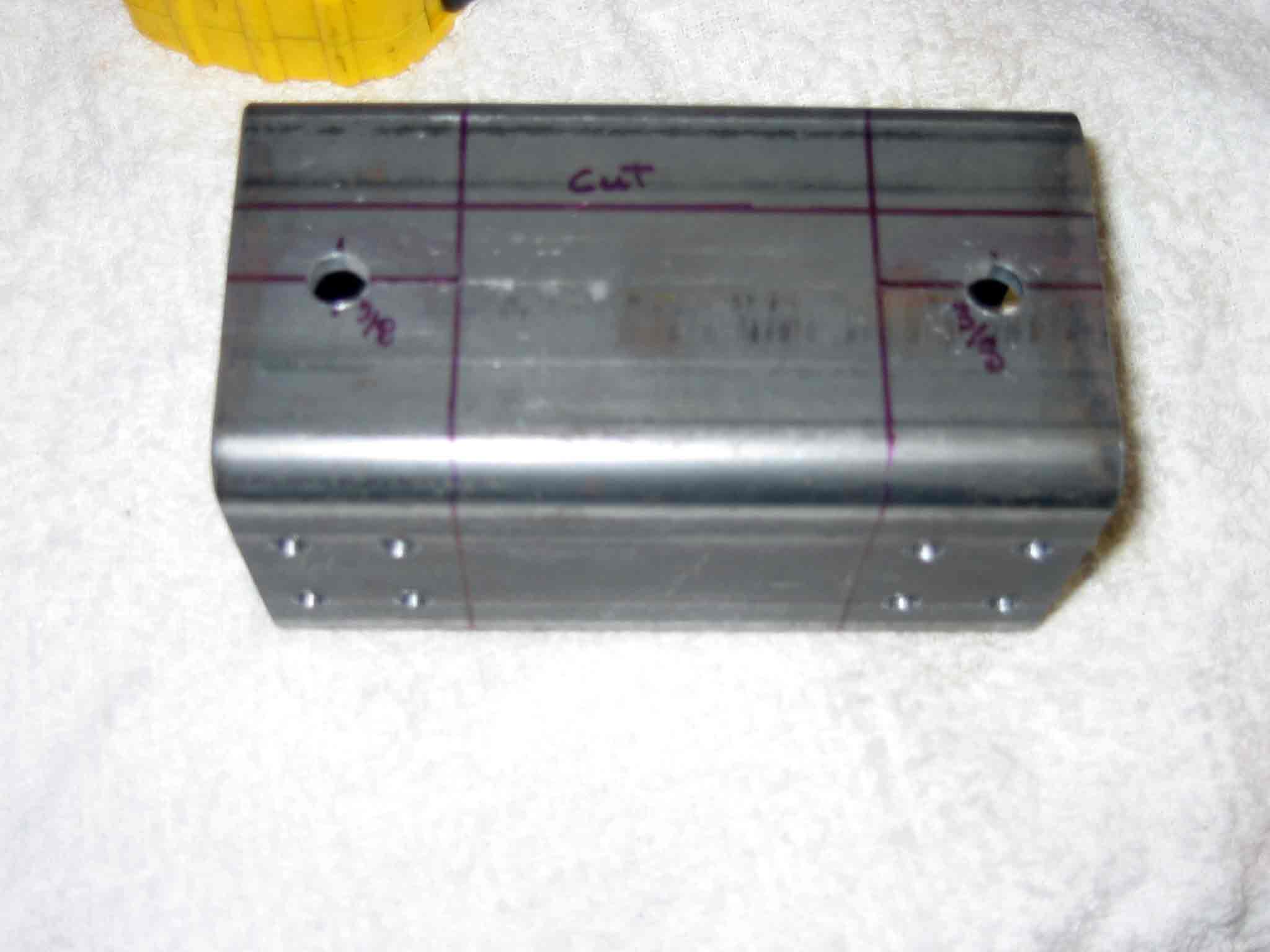
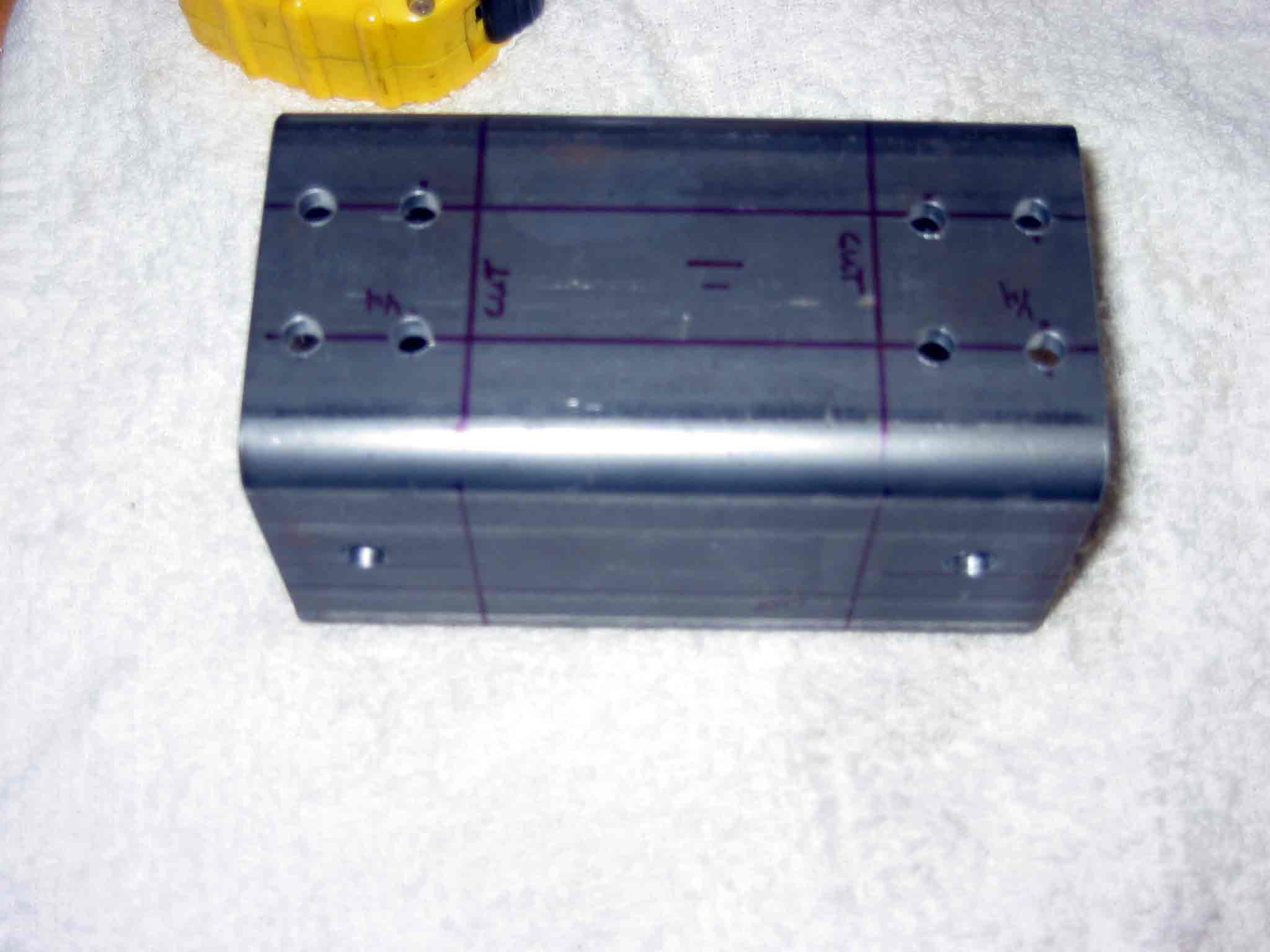
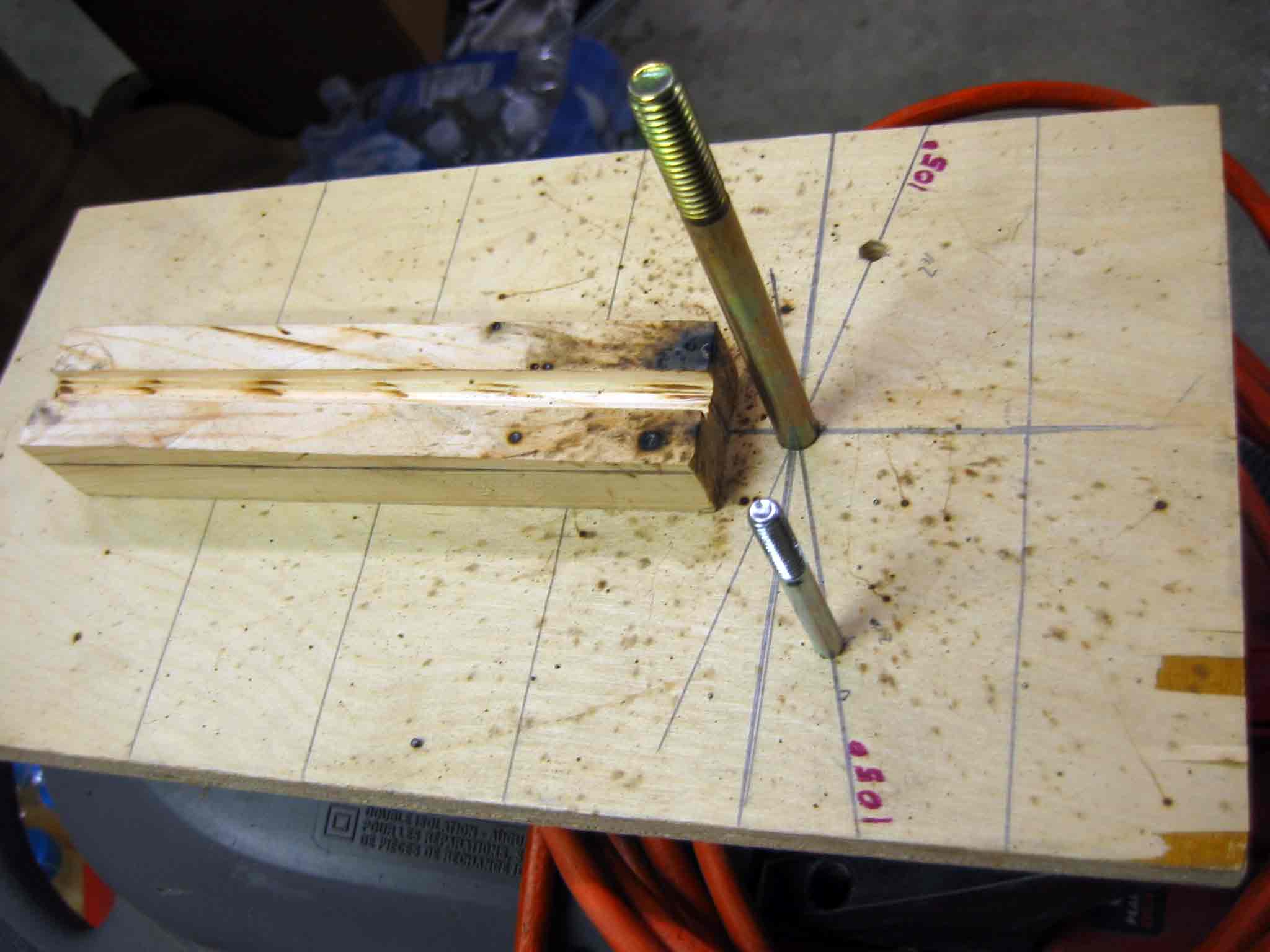
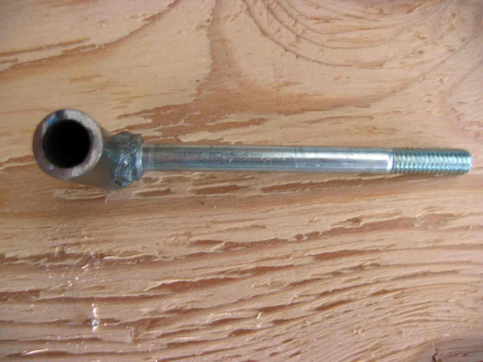
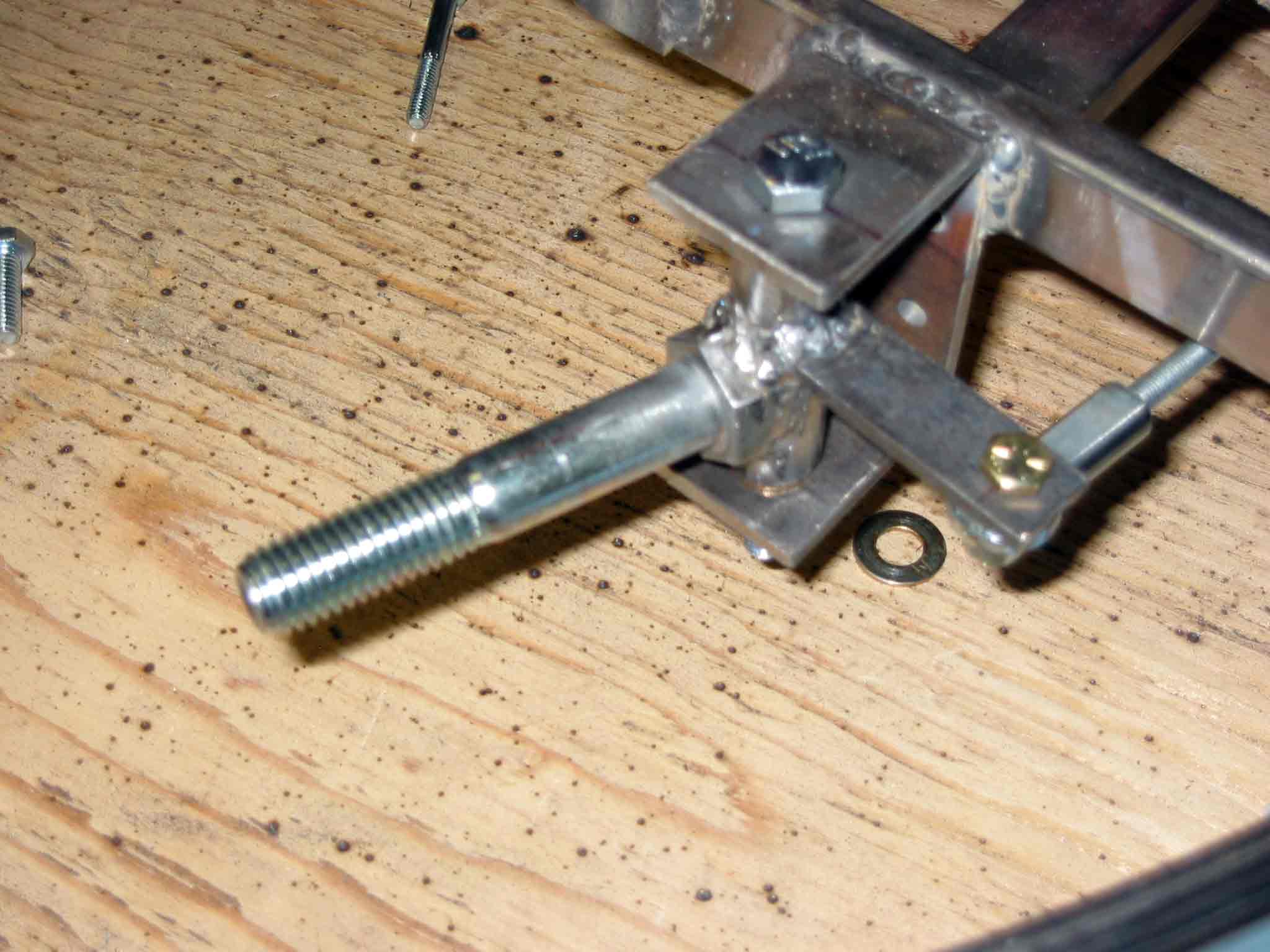
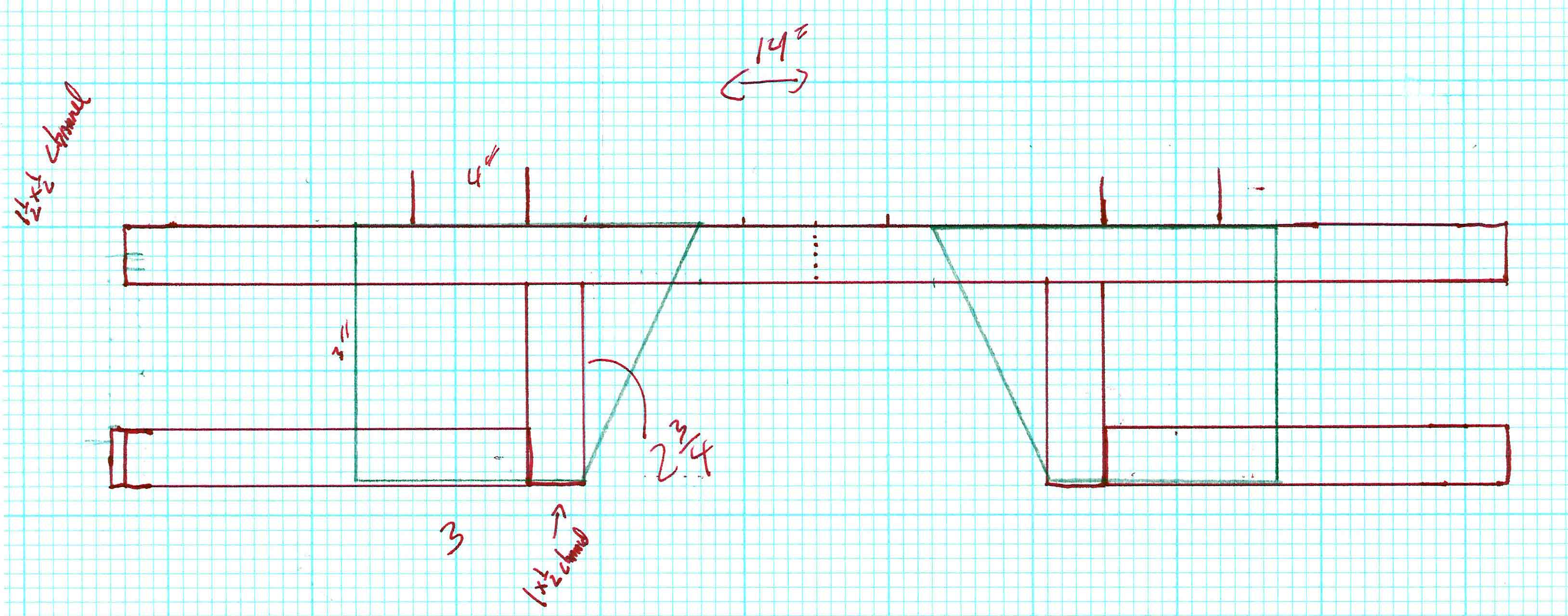
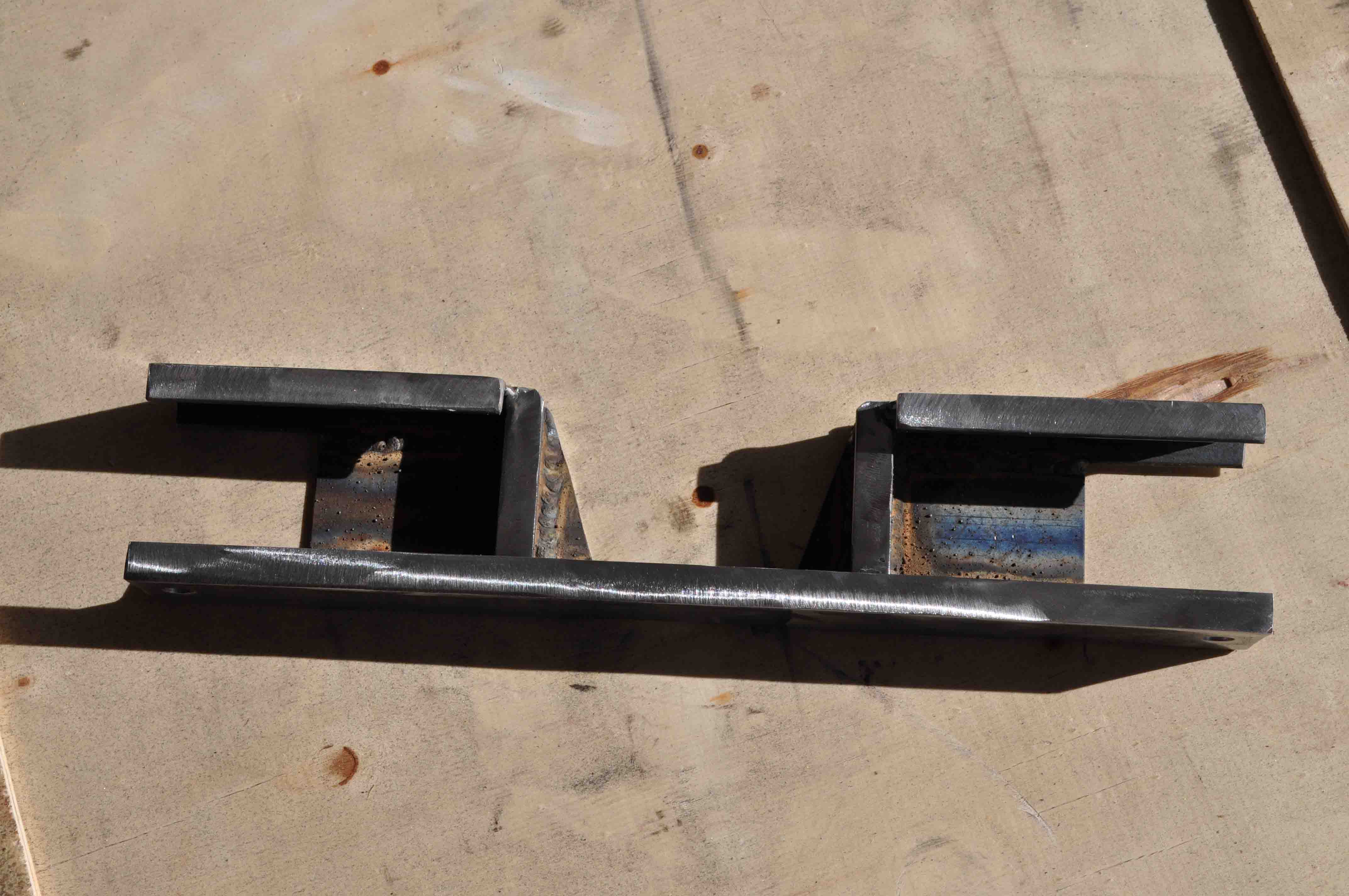
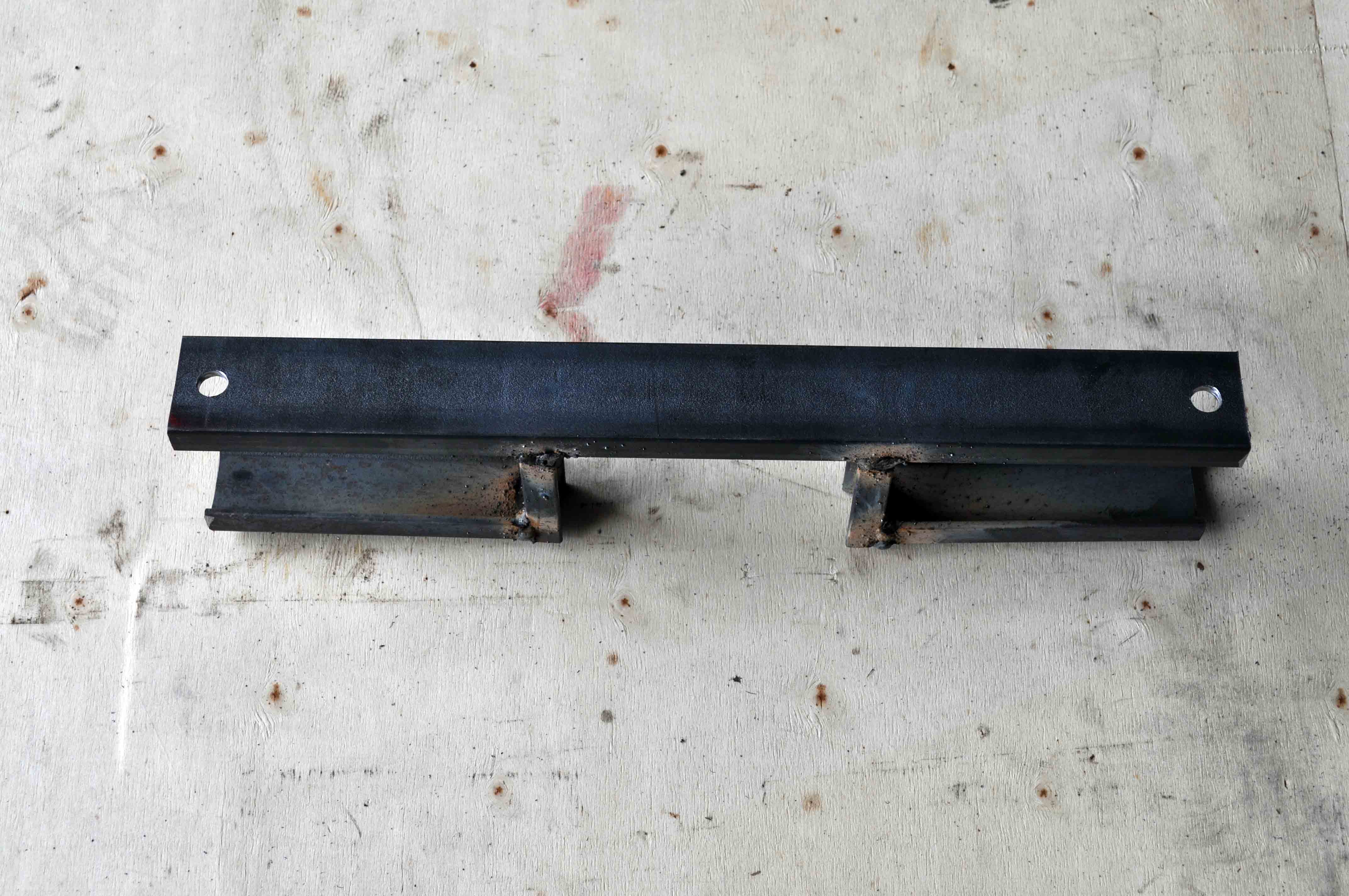
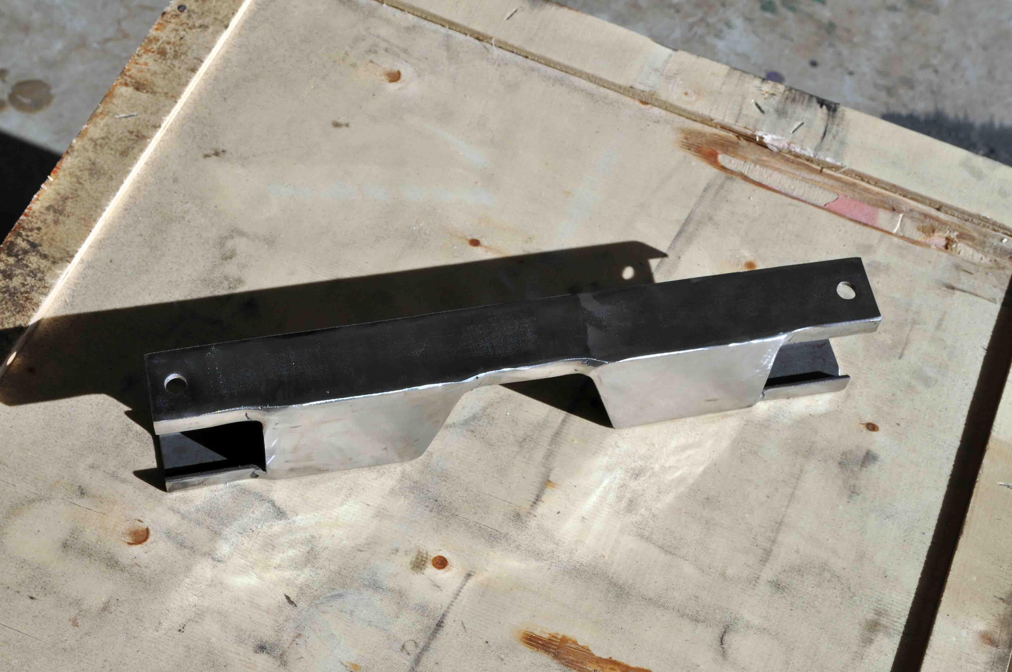
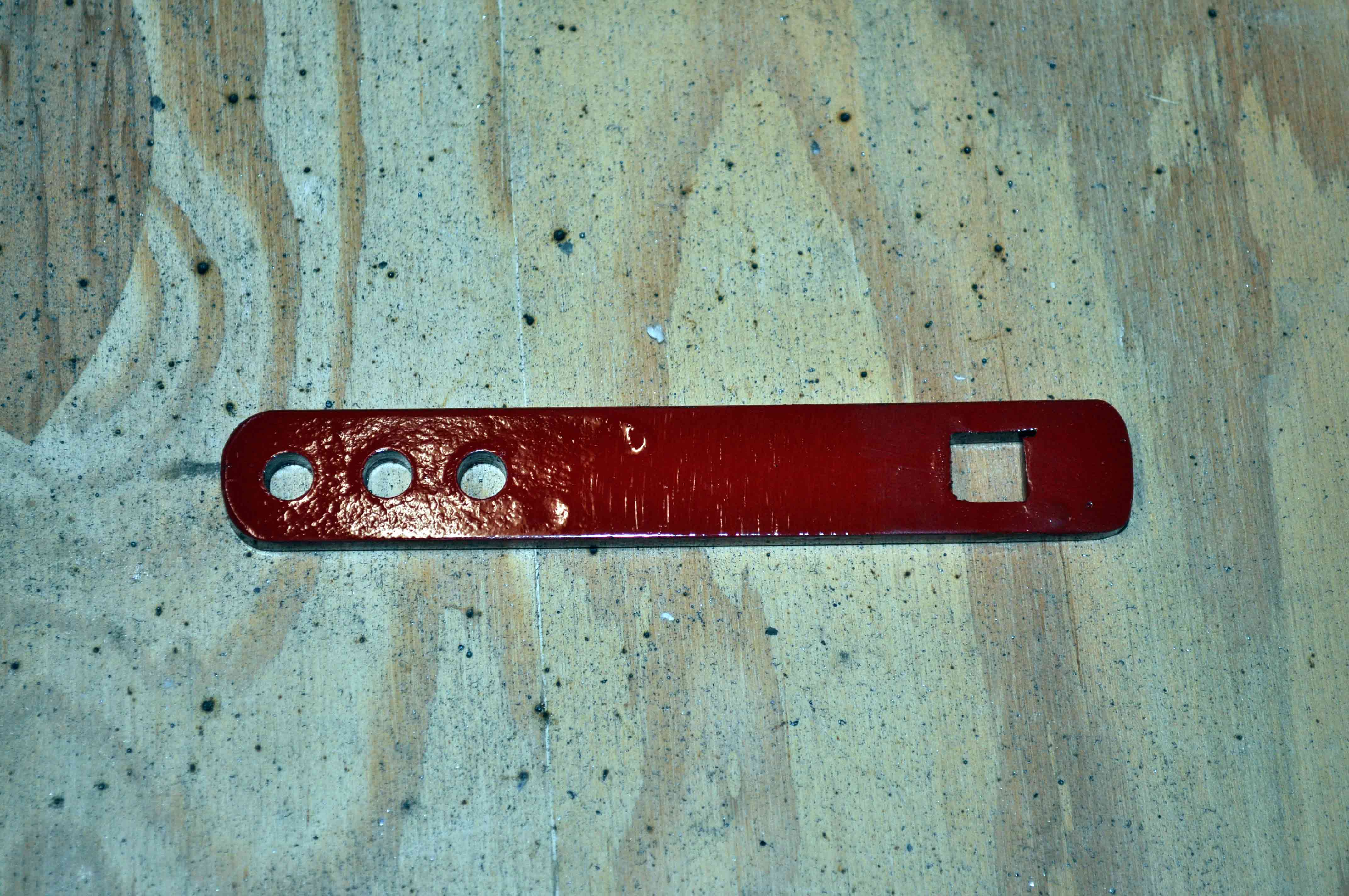
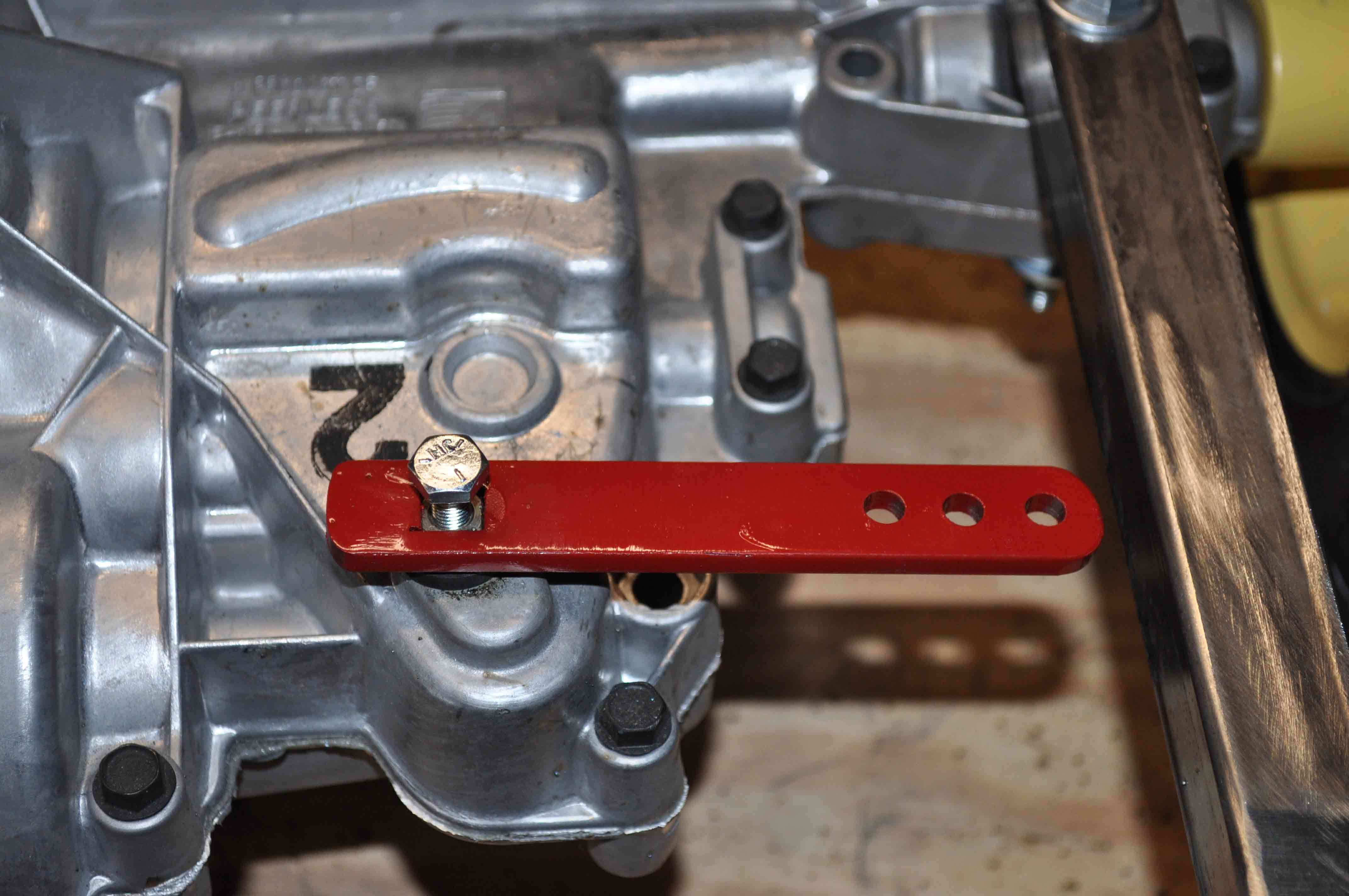
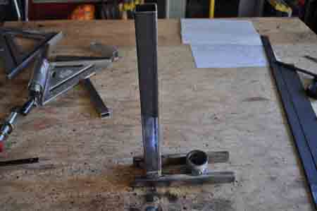
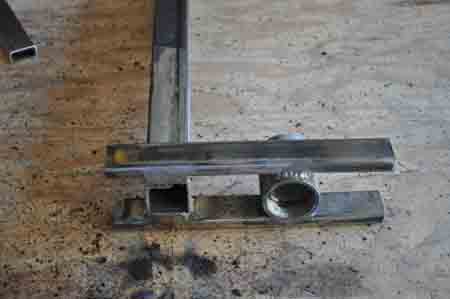
start of the part what will be used to secure the lower end if the brake cable. With the change to using the transaxle with integrated disc break the old break lever was just way overkill so I am switching to a standard bicycle brake handle and cable.
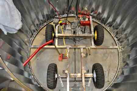
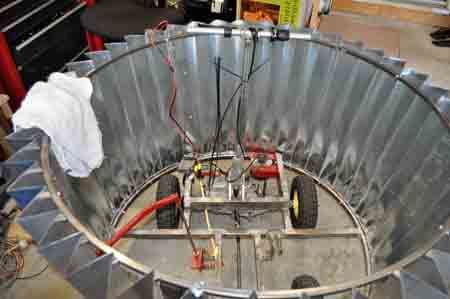
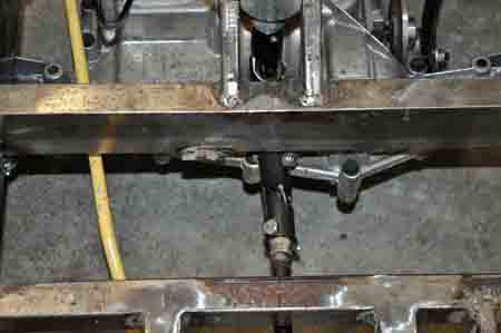
Well after snapping a third pin in the u-joints for the steering assembly I am giving up on rear wheel steering and have cut most mounting points off the frame in order to reverse everything’s position in order make the cupcake a front wheel steering vehicle.
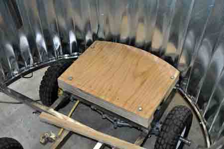
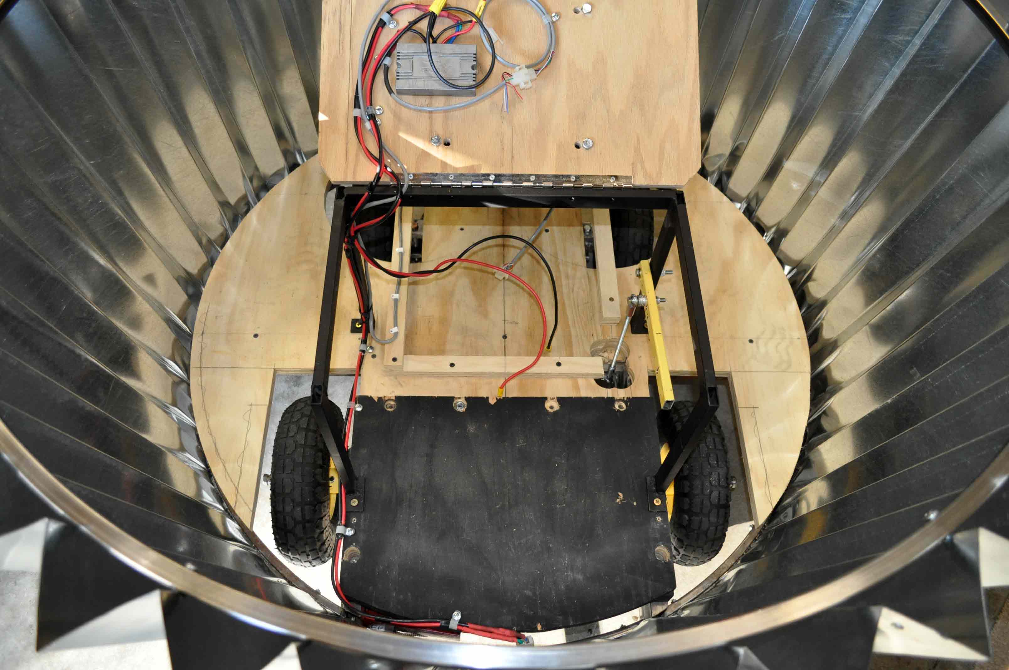
Cover that fits over transaxle that batteries will sit on.
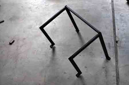
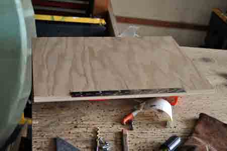
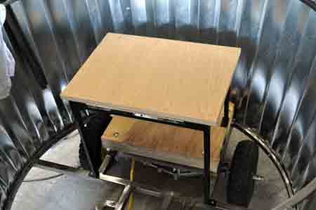
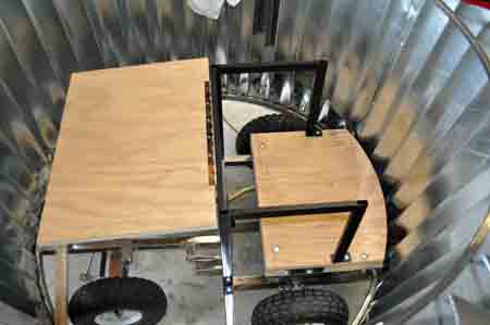
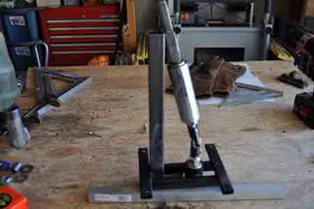
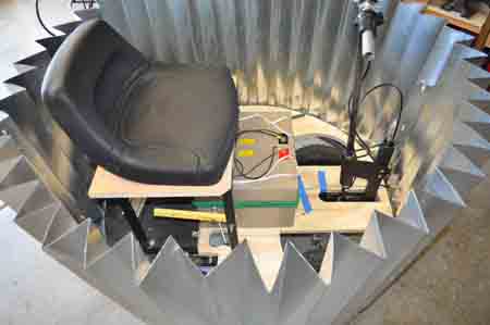
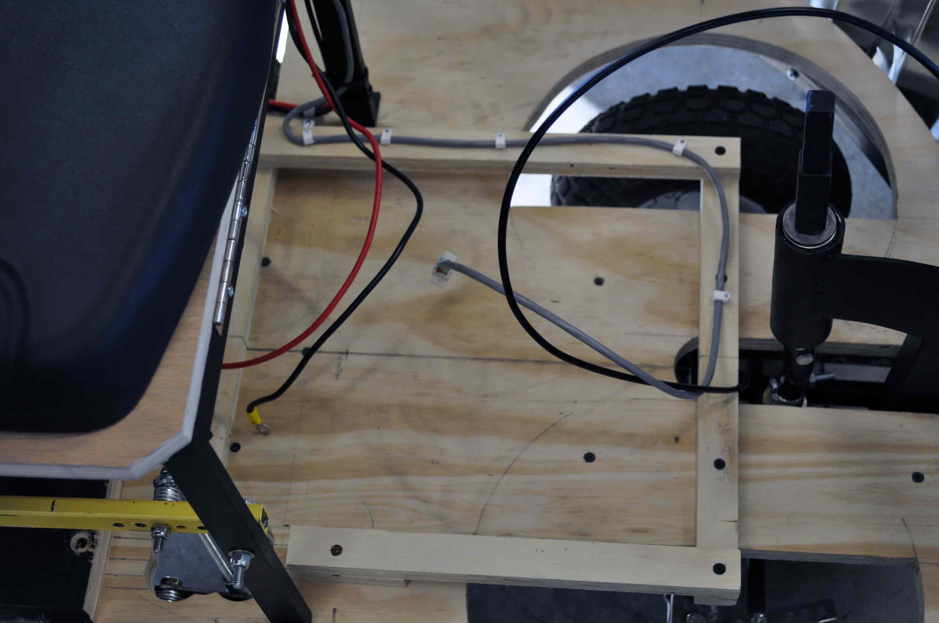
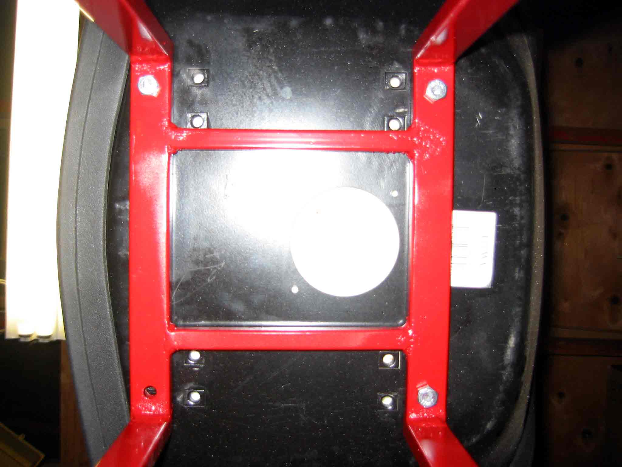
New seat base with flip up top for easy battery access. Additionally I am thinking of mounting the electronics to the bottom of the cover under the seat.
