 |
|
|
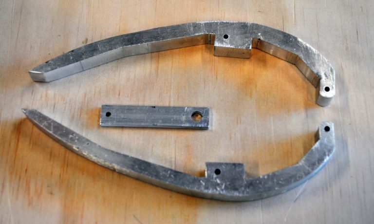
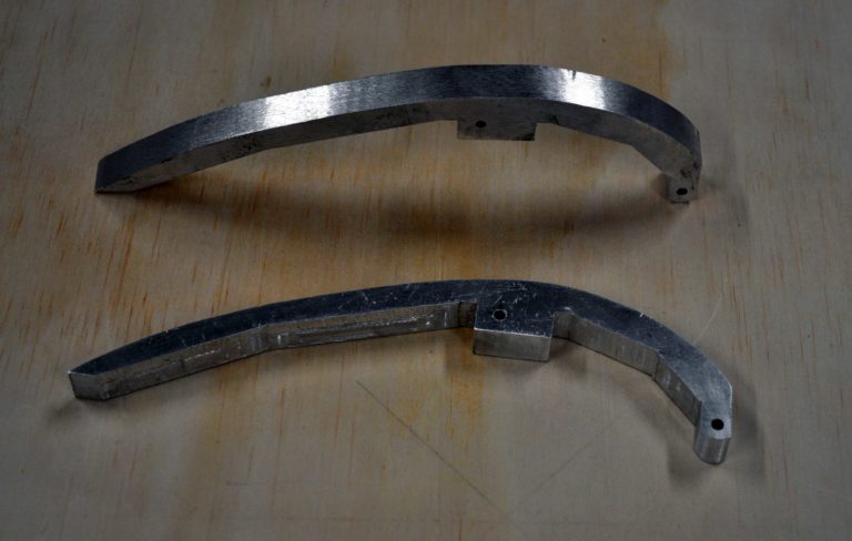
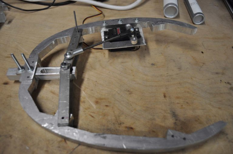
Initial armature milled from ½ inch thick 6061 aluminum plate. While the size for the pod was good, I did not fully take into account the size of a pneumatic cylinder with enough stroke to extend the linkage. So the larger set seen below were created |
|
|
|
 |
|
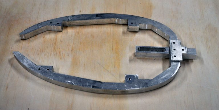
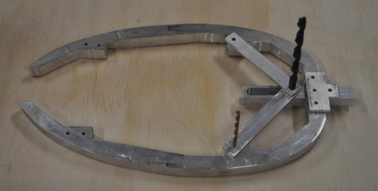
This new longer armature is about the same height at the initial one. Again milled out of 5/8 aluminum plate |
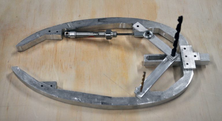
armature with linkage mockedup. The center slide and linkage ensure that the upper and lower parts of the pod will open symetrically from the center. |
| The sliding linkage is made up of a center bar with a 1/4 inch slot cut out and four identical arms. one side of the arms has a 1/4 inch hole and the other has an 1/8 hole for pivoting at the upper or lower armature. One set of arms has additional holes drilled for mounting the cylindar. | 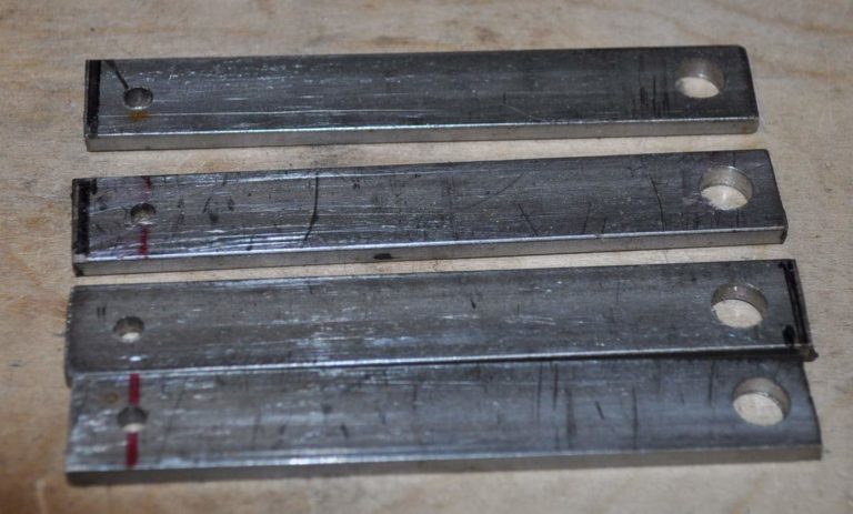 |
|
|
|
|
Linkage mockup with small pneumatic cylinder for sizing test |
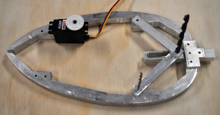
Linkage mockup with standard servo. My intention was to be able to use servo or pneumatic with the armature but pneumatic is normally my first choice |
 |
 |
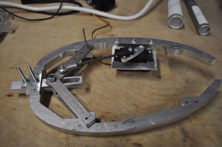
| Final linkage with bars on both sides of center slide to help prevent binding. As this initial build I am thinking as a table center piece getting an air supply to the table center seems problematic so building with servos. |
Testing with the servo showed me that the weight of the larger armature could barely be opened and closed with the standard servo. Coupled with the size was now much larger than I wanted artistically, I took a step back and started justifying the linkage, now that the servo would be used instead of the cylinder. |
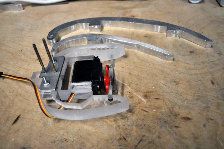 |
At the left the size differences of the initial, enlarged(top) and new build from acrylic can be seen. The third version was made from acrylic because it is faster to build a test armature from as I can cut it out on the band saw instead of using the mill. Additionally the third armature does not extend all the way to the from lip of the pod but will stop about two thirds the way leaving the pod shell to for full support. At this point I am thinking the shell will be vacuum formed from 0.08 hips and should have no problem supporting itself. |
 |
 |
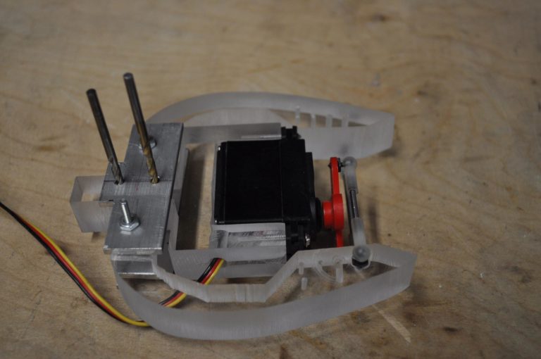
| This third armature was cut from 5/8 acrylic |
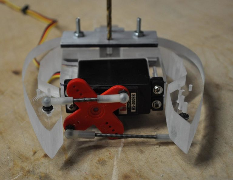
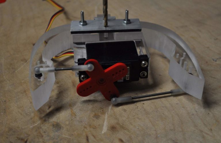
As the servo horn rotates around a central point the upper and lower parts of the armature can move symmetrically from the center line without the more complicated linkage initially used if the servo is simply affixed to the central bar that the upper and lower parts of the armature pivot from. |
|
Testing confirms that this smaller armature without the more complicated linkage is very easy for the standard servo to open and close. I attribute this mostly to the elimination of the slider linkage and not weight of the armature. I believe the sliding linkage had a lot of frictional resistance and mechanical disadvantage that the servo had trouble overcoming.
The image at the right shows the armature in an open state |
 |
| A different view better showing the upper and lower parts of the armature attached to the central pivot and servo holder. | 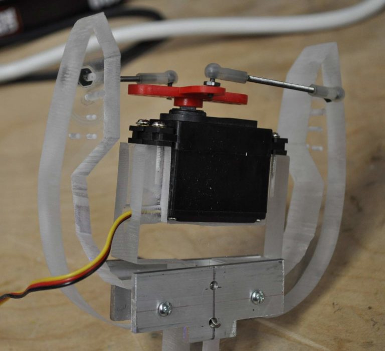 |
| Time to make the shell with the armature prototype working | |
 |
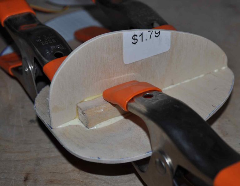 |
| started by tracing the armature to get the half shape including the distance from the center line | With the paper template i made a form to guide me to ensure that the left and right sides of the shell would line up and that the armature would correctly fit inside the shell |
 |
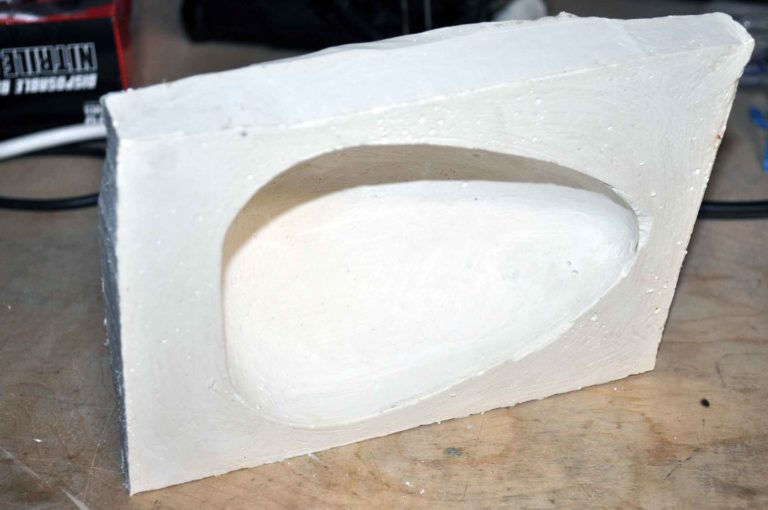 |
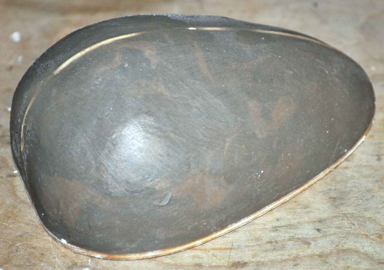
| clay form ready to be molded | As i am only planing on making a couple copies for use in the vacuume form machine I am only making a quick mold from plaster. This plaster mold is coated with a lot of mold release to make sure the resin does not soak into the plaster and can be de-molded |
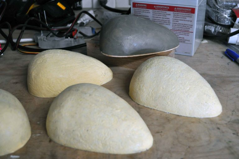 |
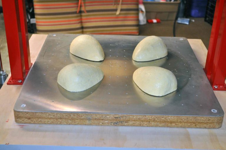 |
| Four pulls from the plaster mold. I had some old por-o-cast haning around so i just used that with some chopped glass fiber, but if i did not have the old resin i would have done these wilth fiberglass instead of making solid pieces | molds ready for vacuume forming |
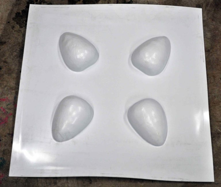 |
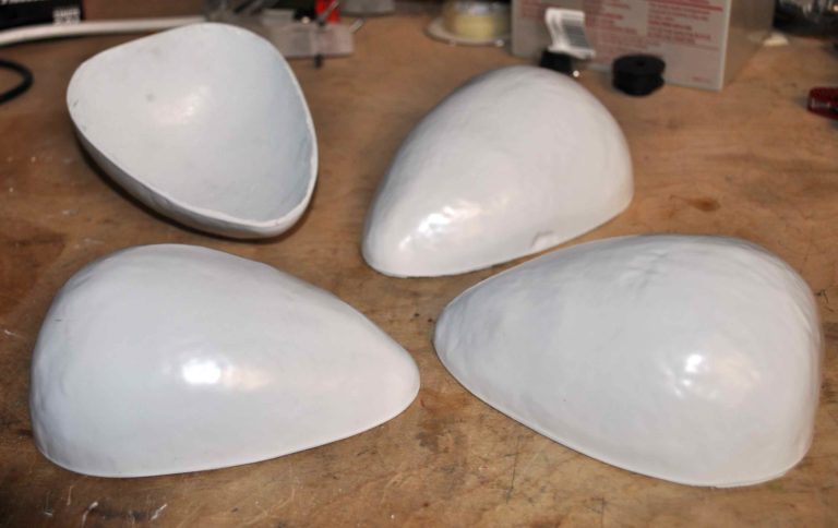 |
| 0.100 HIPS after forming | cutout shells from the sheet |
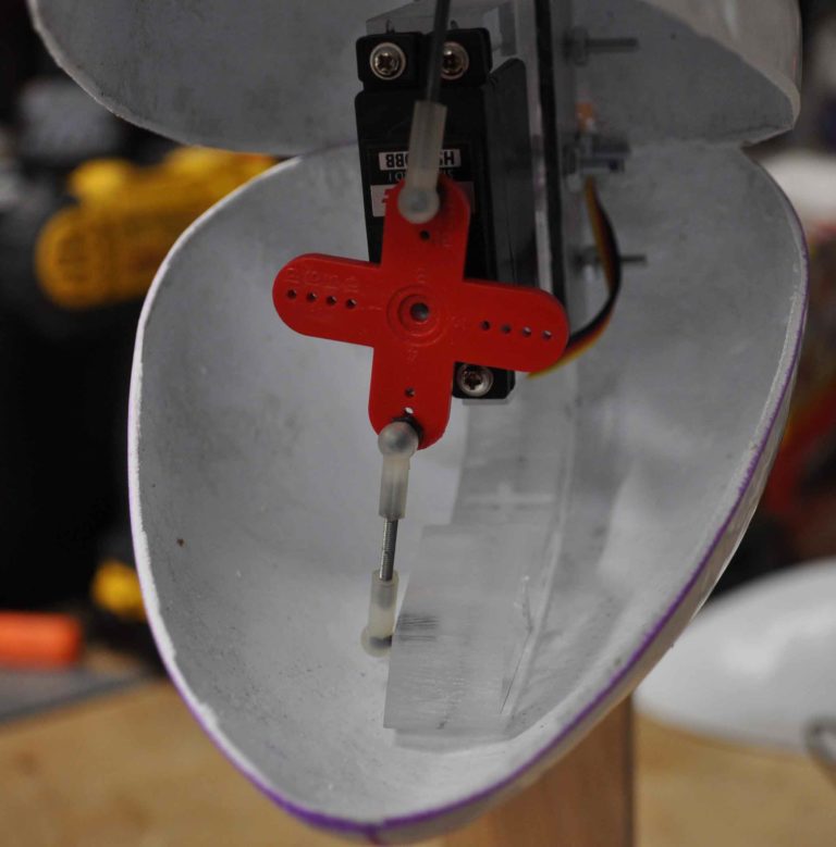 |
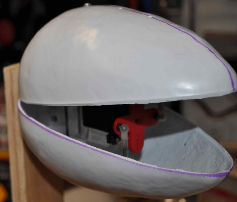 |
| for testing i have just drilled a few holes and used some small round head screws. When I have the design finalized I will have to make a template for drilling holes and cutting the opening in the back. I will also use flush head screws to keep them from showing through the skin of the pod | |
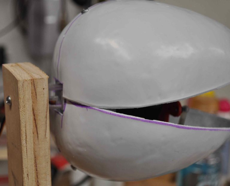 |
|
| Rear view showing the temporary mounting of the mockup | |
|
With the mockup working, I have decided to try using smaller servos so that i can get a second servo in the pod. Originally I was thinking about using cables in the stem for getting some side to side movement but in the pod seams like a better idea after really looking at how much space is in a 1/2 inch steel tube.
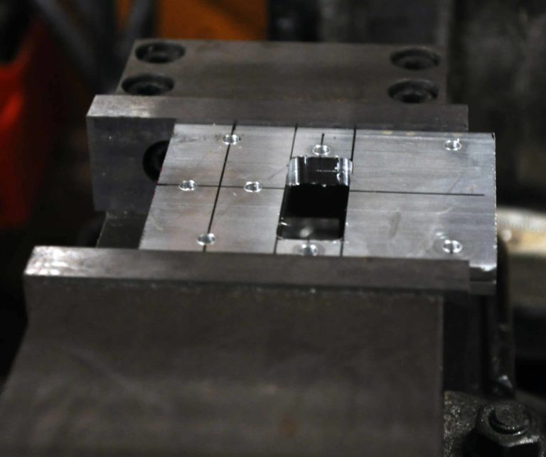
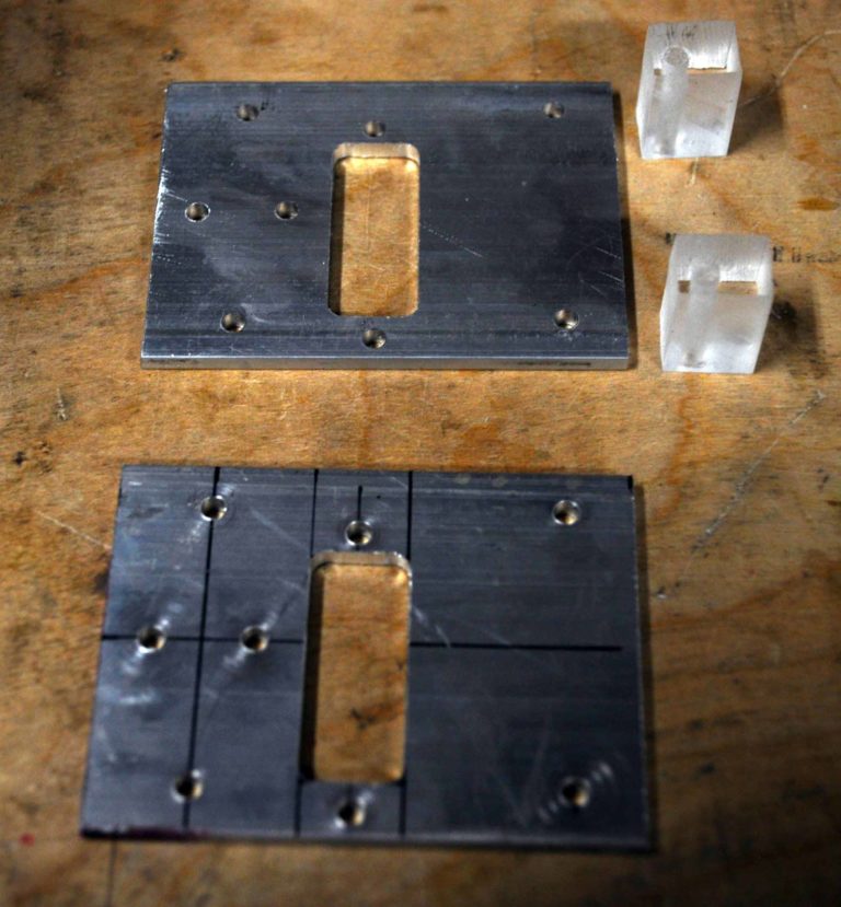
At the left are new side plates for being milled for holding servos and forming the main section of the armature |
 |
 |
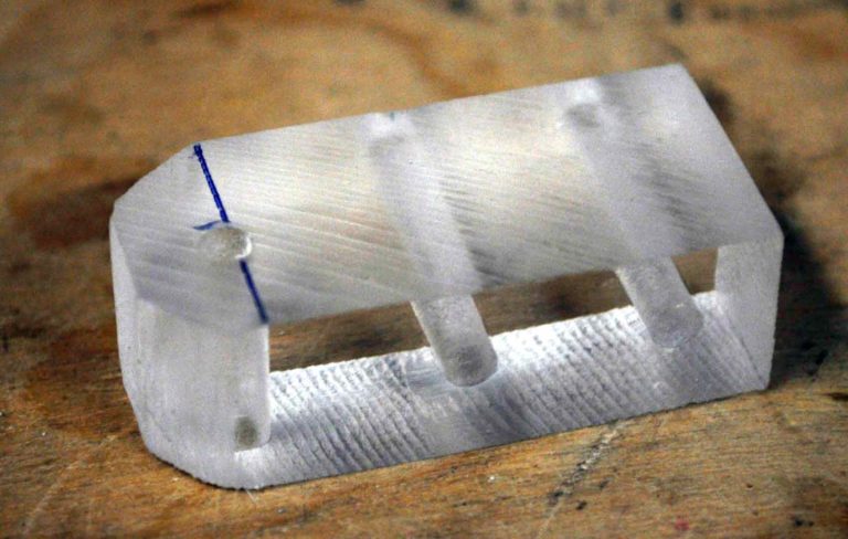 |
| Left and Right sides with front spacers | Rear spacer and pivot mount for pod. This will likly get made out of metal i the final version. |
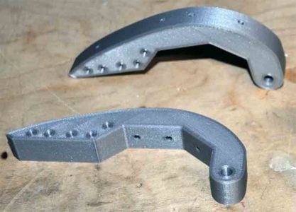
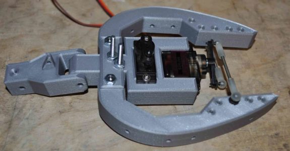
| So I have switched process in the middle of this project and started 3D printing parts instead of milling them from aluminum. This also means I am starting to model the parts out in Fusion 360 and can work out some of the fits before I actually make any parts. | |
 |
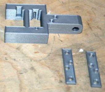 |
| Pod jaw armature modeled and then 3d printed | Center armature for holding jaw and neck servos. The two brackets in the lower corner are for connecting the center bracket to the two jaw armatures. The rectangular recess in the servo bracket are to allow the servo cord to pass as the micro servos are a close fit. |
 |
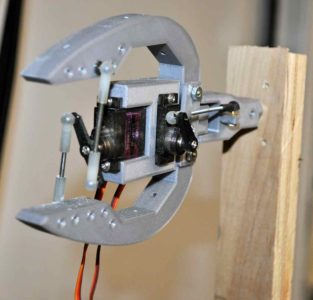 |
| First assembly ready for some testing. Joints all have bronze bushings on 1/8 inch shafts. | on test stand |
 |
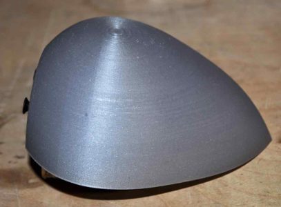 |
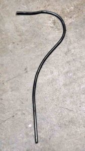
| 5/16 round bar bent into a plant stem shape | 3d print of the inner shape of the armature to use for sculpting the outer skin on |
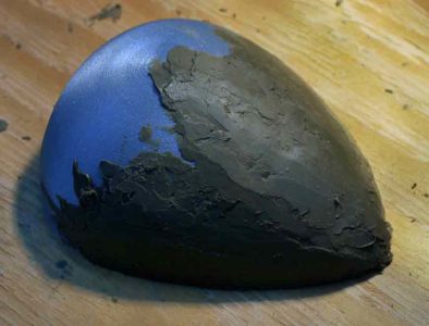 |
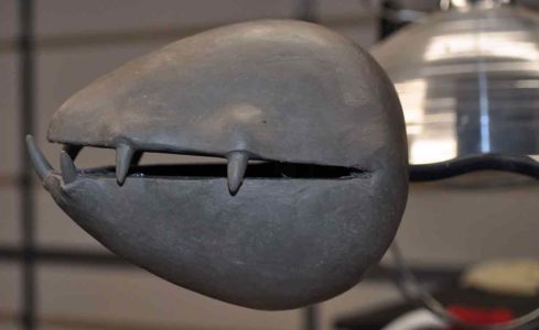 |
| with the clay good and hot I slowly built up a few layers of monster clay to about 3/8 inch thick | |
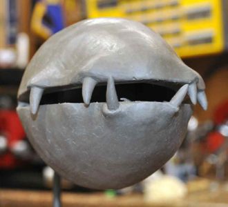 |
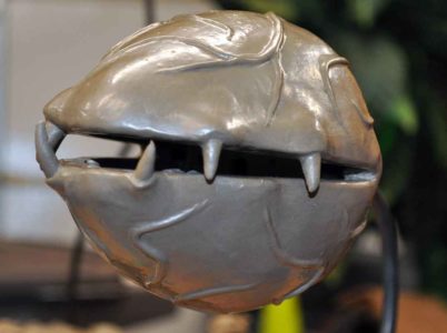 |
| clay mostly smoothed before adding vain. At this point the clay is room temp and very hard. To the point that i used 220 grit sand paper to help smooth the clay | I was having trouble getting the clay to smooth, so i tried flame polishing the clay like one would do with the edge of a piece of clear plastic and it worked better then the normal chemicals and was quick. a little more touch up and it will be time for molding. |
 |
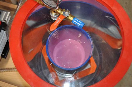 |
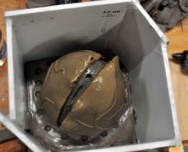
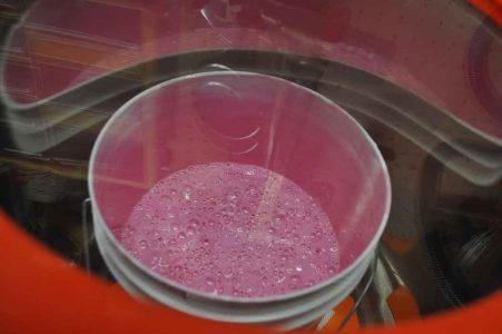
| Pod ready for first part of three part mold. | pink goo degasing |
 |
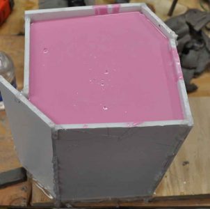 |
| always amazed with how much air comes out of the mix | Moldmax 30 covering the pod |
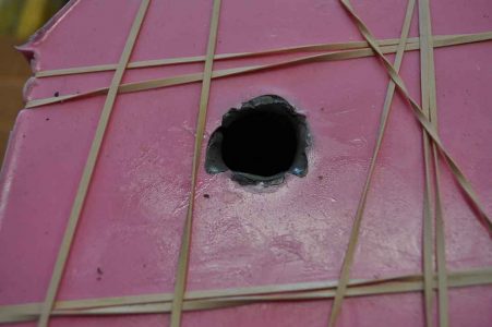 |
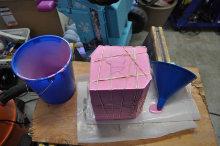 |
| After the two outer molds were cured, the molds were lined with about 1/8 to 1/4 inch of clay so that an inner mold could could be made. this will allow a skin to be made for the final project | more pink goo filling the inner cavity |
