Over the years I have wanted a good device that would convert spoken audio tracks into jaw movement. I have tried a few over the years and find that they tend to just drive movement based on volume of the audio track. Additionally they are all servo based leaving me with the additional problem of how to drive jaw movements that are based on pneumatics. About ten years ago I tried making my own audio to pneumatic controller but never got happy with the results and ending up moving on to other things. This has left me hand sync’ing jaw movements to audio using either a key banger or Cubase.
With some time under the bridge I have once again decided there must be a better way to sync jaw movement to audio besides manually setting up the movements to match the audio. However this time there are some newer components like the MSGEQ7 that analyze different parts or the audio spectrum and measure each segments amplitude. I am going to use this to focus in on the normal parts of the spectrum where spoken word tends to be and then use a microcontroller to interpret that and drive either a servo or a pneumatic actuator. To compensate for the actuators lack of positional repeatability I am going to add a feedback loop for measuring the amount of jaw movement.
The Build
 |
 |
| Raw PCB fresh from manufacturing | I start by soldering all the surface mount components. As this was just a prototype I have dabbed a little paste onto each pad and then hand placed all the parts with tweezers. Once all the smd’s were placed I used my hot air soldering tool to heat and flow the solder. |
 |
 |
| Next I moved on to the thru-hole parts starting with the lowest and working my way to the tallest parts | Fully assembled board less the IC’s that need to be inserted into sockets |
 |
With a first pass at the code written and loaded into the AVR, it was time to plug it in and see if a servo moved to an audio input… No surprise it did not work as expected. Though I was figuring it might not as I am a bit rusty programing microcontrollers as it has been like 8 years. Ok, let’s go do some testing to make sure the hardware is working as expected. Somehow I have a sneaky feeling I am trying to stuff a word size variable from the ADC read into a byte size variable for the servo position, will have to check that if this does not work as expected the first time. |
| Bottom of the assembled board | |
 |
 |
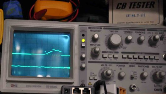
| board hooked up and attached to a scope. |
And yes, I still use my old analog scope from time to time. Sure a nice digital one with logic analyzer features would be nice but let’s face it I use this thing once in a blue moon and it tells me what I need to know. But it is a brick. |
 |
|
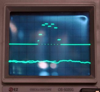
| Closeup of the measurements. The lower line is the audio input and the upper line is the output of the 7 band EQ showing the intensity of each band segment. Note the seven small lines. I suspect there is a little noise in the test lead to test lead so I am not concerned about the little ripple in the EQ output. But based on these results the EQ and the code to reset and strobe the EQ is working just fine. | |
